
Babowana said:What about this . . . ?
Seasons greeting

April 1. ?
it will not work

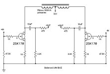
carpenter said:I went back to the basic JfetBOZ and drive it with 15 volts. I still use the Plitron 1000VA transformer to choke load the drain (no resistor).
Think the 1000VA rating is adequate?
That's very nice. If I may:
Try increasing the value of the Source resistor on Q3, raising the
voltage driving Q3 for more current through Q1,2 (up to 10 mA
each), and RC filtering the drive to R13 to remove zener noise.
😎
Try increasing the value of the Source resistor on Q3, raising the
voltage driving Q3 for more current through Q1,2 (up to 10 mA
each), and RC filtering the drive to R13 to remove zener noise.
😎
Nelson Pass said:That's very nice. If I may:
Try increasing the value of the Source resistor on Q3, raising the
voltage driving Q3 for more current through Q1,2 (up to 10 mA
each), and RC filtering the drive to R13 to remove zener noise.
😎
Thank-you Nelson. 🙂
I'm reading your suggestions two different ways:
Are you saying that raising the Source resistor on Q3 raises the voltage driving Q3? Or, are you suggesting that I perform three things:
1. Increase the value of the Source resistor.
2. Increase the voltage of the negative supply.
3. RC filter the drive to R13 (terminology is a bit above my head).
Regardless, I'm going to explore your suggestions any way I can.😀
Nelson Pass said:That's very nice. If I may:
Try increasing the value of the Source resistor on Q3, raising the
voltage driving Q3 for more current through Q1,2 (up to 10 mA
each), and RC filtering the drive to R13 to remove zener noise.
😎

Attachments
Zen Mod said:
Where have I seen that?....🙂
One step more, and it will become a

Choke loaded
? 😀Vix said:
Where have I seen that?....🙂
One step more, and it will become a
Choke loaded
😉
nope - Brunhilda will be choke loaded , for personal use ;
for public use - it will be CCS loaded ( from top and above) , with choke loading as option
Honest, Choky, I haven't been copying your ideas!😱
I think I'm supposed to raise the gate voltage to the CCS, this in turn requires that I raise the source resistor to maintain proper current.
At least, this is what I did earlier this morning.
But, after some mental tampering, I lowered the value of the zener in order to lower the left-over voltage, which allowed me to run a lower value resistor, which I thought (incorrectly perhaps) was the thing to do.😀
carpenter said:Honest, Choky, I haven't been copying your ideas!😱
I think I'm supposed to raise the gate voltage to the CCS, this in turn requires that I raise the source resistor to maintain proper current.
At least, this is what I did earlier this morning.
But, after some mental tampering, I lowered the value of the zener in order to lower the left-over voltage, which allowed me to run a lower value resistor, which I thought (incorrectly perhaps) was the thing to do.😀
you can try that mishmash of "your's" and "mine" .........
my ideas .......
boiled water ......... I'm just a kidoe , walkin' in someone's footsteps all the time ....
but - what's important - doing that with pure heart , with joy ....... 😉
edit:
Papa told ya that - in purpose of increasing dynamic resistance of that CCS .
remember - in LTP - longer the tail , better symmetry ..........
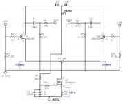
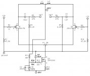
carpenter said:I increased the value of the Zener and raised the CCS source resistor:
John,
You can halve the Source R value of Q3 to get double the CCS current that you have. Each half of your circuit will then get close to the NP recommended current. You can monitor the voltage across the jfets D-S as you adjust P1 to balance current draw after warm-up. By putting a high series R with the zener before the Gate R junction plus the parallel cap you have should effectively filter the zener noise.
Blues said:
John,
You can halve the Source R value of Q3 to get double the CCS current that you have. Each half of your circuit will then get close to the NP recommended current. You can monitor the voltage across the jfets D-S as you adjust P1 to balance current draw after warm-up. By putting a high series R with the zener before the Gate R junction plus the parallel cap you have should effectively filter the zener noise.
Hi Blues,
I thought I was to raise the source resistor's value--but I will lower it as you suggest to hear what there is to hear. Currently, there's 4.4mA current for each Jfet. I thought Nelson suggested 10mA per jfet as a "range" i.e., not to be exceeded.
Are you suggesting that I parallel a resistor with the zener and cap? I'm apologize for being a bit thick-headed.😉
BTW, with the mods in my last drawing, the amps sound very pretty--silky--smooth as a baby's behind.
carpenter said:
Hi Blues,
I thought I was to raise the source resistor's value--but I will lower it as you suggest to hear what there is to hear. Currently, there's 4.4mA current for each Jfet. I thought Nelson suggested 10mA per jfet as a "range" i.e., not to be exceeded.
Are you suggesting that I parallel a resistor with the zener and cap? I'm apologize for being a bit thick-headed.😉
BTW, with the mods in my last drawing, the amps sound very pretty--silky-smooth as a baby's behind.
woodie
on your last schm :
I= (Uzener-Ugs) / R
so :
I=(9V1- 4V) / 511 = 10mA
you can always presume that Ugs is ~4V and correct resistor value later
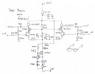
so - if you use greater neg voltage , you can also use zenner with greater voltage (say 27V , whatever) and calcualte adequate resistor .... (watch at dissipation of that resistor) ...... that way you increase dynamic resistance of sayed CCS
put 10k resistor between gate resistor and zenner ; put cap from gate resistor to gnd
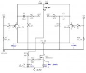
carpenter said:Thanks Choky. So, I'm going to try something like this:
good for start
try that cap from gate in both ways - as in schmtc and also routing it to minus PS ........ and choose what's better for you
you can also tweak gain of stage adding resistors from both sources to trimpot , in purpose of source degeneration
decrease reference resistor in CCS , in purpose of increasing current through jfets ; if you have BL or V iteration - you can go up to 10mA per side , as Papa wrote ;
if you have J310s (cheap as drek) , you can go all way to 12-14 mA per side ...... listen and decide ( if you don't have any , or it is to much fuss to purchase them - use
ones ; in case that you burn them , I'll send you new ones for .......... coffee on next BAFif you don't need much gain (say - 2 to 4 times) , you can make little SUSY of it ( you know how ?
 )
)and - yes - you can try ( and like ) cascoding those little critters ; just copy what you see in
- Home
- Amplifiers
- Pass Labs
- JfetBOZ mods