These puppies are trough hole: https://eu.mouser.com/c/semiconduct...t/?mounting style=Through Hole&technology=GaN
I can’t get LTSpice to work on my Apple M1 (I’m too stupid for this) but if I get it working I’ll do some simulations as well.
Need to design something firth a tube frontend and a **** ton of parallel transistors in the output. Each with it’s own bias
I can’t get LTSpice to work on my Apple M1 (I’m too stupid for this) but if I get it working I’ll do some simulations as well.
Need to design something firth a tube frontend and a **** ton of parallel transistors in the output. Each with it’s own bias
2sk182es is great but you could also simulate one:@savu
That would be really interesting, I was looking also at them. I have run LTSpice circlotron simulation for them and got remarkable results!
The problem I had with them is that I had much difficult time to use their package in my platform and application. And also check their useful area, they are not meant for Big Class A currents, practically they are not meant to dissipate more that 40W each . But you mentioned you are going to use many of them in parallel, so you can go for it!
Regarding the heatsink, i would suggest that since circlotron design permits adjusting of Class A current, you just build it and reach the point your heatsinks can manage (in summer 🙂 )
And if your' re searching the tube like sound, you can always use 2SK182ES! That is my current setup but with these I found difficult to go over 60W. But they have best sound (at least for my ears)
Attachments

The one that could fit is TP65H015G5WS. It is the one that has acceptable SOA. But will fit in project in more than 6 months from now 🙂These puppies are trough hole: https://eu.mouser.com/c/semiconductors/discrete-semiconductors/transistors/mosfet/?mounting style=Through Hole&technology=GaN
I can’t get LTSpice to work on my Apple M1 (I’m too stupid for this) but if I get it working I’ll do some simulations as well.
Need to design something firth a tube frontend and a **** ton of parallel transistors in the output. Each with it’s own bias
For 2SK182ES simulation, very impressive but you are on non feedback thread 🙂

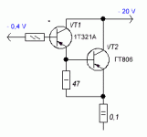
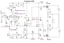
Removed transistor T2 (KP2). Nothing has changed, stability has remained the same. I attached darlingtons on germanium transistors instead of mosfet. I used germanium diodes D303 in the power supply. On massive radiators, the current is very stable. MOSFET laterals P- channel are also well suited for KP2 circuit. But the output impedance will increase to 2.5 ohms.
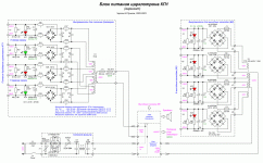
https://www.profusionplc.com/type/lateral-mosfet
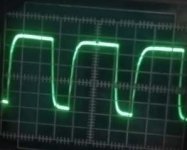
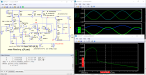
Square wave - 60 kHz;
https://www.profusionplc.com/type/lateral-mosfet
Square wave - 60 kHz;
Attachments
Attachments
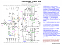

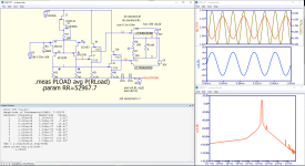
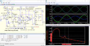
Calculation of the Circlotron on silicon carbide transistors. Operates in Class A without overall negative feedback. In the first calculation, resistors are determined to operate at a current of 2A. Distortions are determined at an output power of 1 W and a load of 8 ohms. Intermodulation distortion is calculated.
Attachments


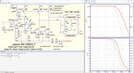

Probably, the decrease in THD depends on the introduction of local feedback in the differential cascade (R6, R9 - 1.5 k). The last circuit on jfet looks like this. Great sound! The IRL540N fit well into that circuit. There is also a local feedback R5, R6, but the values of the resistors (36 ohms) need to be selected at a minimum of THD.
P.S. The BJT circuit is just a simulation. It was not collected in hardware.
P.S. The BJT circuit is just a simulation. It was not collected in hardware.
Attachments
For 2SK182ES simulation, very impressive but you are on non feedback thread 🙂
Sorry, i don't want to sidetrack but why not negative feedback?
This is serious question since im beginner. I have been reading about different feedback and what they do to sound.
I used to think that negative feedback is all evil since amplifiers that use it does not generally sound too "open, flowing, organic, breathing" for me..
But then i encountered 3 amplifier, rh84 tube amplifier that uses littlebit local feedback? Threshold t200 that uses minimal feedback, and luxman l58a that uses Duobeta feedback system.:
( explanation of duobeta: https://audiokarma.org/forums/index.php?threads/luxmans-duo-beta-amps.59555/ )
All those amplifiers uses feedback and goes into catgory of "open flowing organic sound", so:
-What is your experience with feedback? Can it work with careful design and controlled amount (little)?
The problem of setting the offset on the gates of MOSFETs has been solved. Coarsely can be adjusted by changing the value of the resistors 4.6 kOhm. Fine-tuning by changing the negative voltage of the stabilizer.
Attachments
Last edited:
Hi Sébastien! I took these works in the simulator here:
https://kazus.ru/forums/showthread.php?t=122489
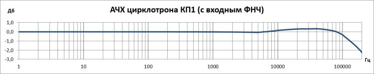
I assembled this circlotron on the BC547/BC557, but the frequency response of the differential cascade is linear only up to 12 kHz. And I don't know where the reason is. But the maximum amplitude is 16.5 V. Maybe you need to change the circuit ... You laid out an interesting circuit. Can you see in more detail?
https://kazus.ru/forums/showthread.php?t=122489
I assembled this circlotron on the BC547/BC557, but the frequency response of the differential cascade is linear only up to 12 kHz. And I don't know where the reason is. But the maximum amplitude is 16.5 V. Maybe you need to change the circuit ... You laid out an interesting circuit. Can you see in more detail?
Last edited:
I didn't understand this question. Can you formulate this question differently?Hi jpatay, why not with a follower on vas ?
I was suggesting replacing Q7 Q8 Q10 Q11 with another circuit that you have already seen on my website, a voltage amplification stage with a directly attached emitter follower.
We need to look at the whole circuit. What will be the next cascade.I was suggesting replacing Q7 Q8 Q10 Q11 with another circuit that you have already seen on my website, a voltage amplification stage with a directly attached emitter follower.
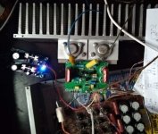
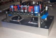
I have settled on this circuit of KP2. I've been listening to music for a few days now. The sound is excellent. On large radiators, the output stage current is stable. Due to the local feedback of R5, R7, there is less distortion. The output stage is powered by a switching power supply.
The current of the output stage is tuned to R4.
The current of the output stage is tuned to R4.
Attachments
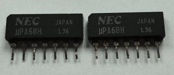
I took out the UPA68H from the non-working Sansui amplifier. The initial current is 2 mA. КПС104Г can be replaced with UPA68H. At first, I used mosfets IRFZ46N (Umax-55V). The sound was excellent, but the power supply to the output stage was 30V and in one channel the mosfets failed. I had to replace them with IRFP150N. Their capacity is twice that of IRFZ46N. And the sound got a little worse. I was too lazy to disassemble the pulse source and unwind the turns of the transformer.
Attachments
- Home
- Amplifiers
- Solid State
- JFET-only Circlotrons without negative feedback