Yes, it was published as a minimum-parts exercise to show what the Jfet can do. The "Jfet BOZ" was never a real project, it merely grew legs of it's own and started running as more and more people tried it. It's surprisingly nice.
Thanks for your responses.. Like I said, my intention isn't to be critical of his design. In fact its quite the opposite. I'm trying to figure out what makes them sound so good yet appear so simple 🙂
Last edited:
Jfet boz sounds good for such few parts. If you want innovation look at the ba3 front end or vfet 2 front end. If you want state of the art you probably have to hack a pass labs computer or get inside Nelson's brain.
Thanks for your responses.. Like I said, my intention isn't to be critical of his design. In fact its quite the opposite. I'm trying to figure out what makes them sound so good yet appear so simple 🙂
Less is always more if done correctly.
dc input- can i connect jfet boz directly to tda1543 dac? 2.2v dc input there. how about b1? thank you.
Since the jfet boz is DC coupled (no input capacitor), any DC offset will make the Jfet operate in a different region. With 2.2VDC you will get a less linear response from the amplifier and you'll be operating near clipping actually. I would advise a coupling cap for AC coupling in the present case. The B1 is AC coupled, the DCB1 diy variant is not.
Please correct me if I'm wrong, folks.
Please correct me if I'm wrong, folks.
Last edited:
It really depends on the load you will be driving. The lower impedance load the less inductance you will need for acceptable low frequency response. Now here is an article that takes this type circuit and applies it to a power amp. In this case 110 mh was used and the load was 8 ohms. But if an 80 ohm speaker was used it would have needed 1100mh for the same low frequency responce. But now suppose your load is 800 ohms you would now need 11H. By the way the tube crowd when using a choke anode load may need something in the 100 H to 600 H range ! Well here is the article with some math to play with !
http://www.diyaudio.com/forums/diyaudio-com-articles/202480-l-amp-simple-sit-amp-part-deux.html
http://www.diyaudio.com/forums/diyaudio-com-articles/202480-l-amp-simple-sit-amp-part-deux.html
Does anyone know where to source a Boz pcb? Jim's audio on ebay is sold out and I cant seem to find them elsewhere.
Thanks for any assistance.
Thanks for any assistance.
Disregard, emailed Jim's on ebay and he put some up again. Now on to finding the case and other parts..
Our very own store has real nice cases and jfets. Mouser for the rest.
Just thought I would add, do yourself a favor and build the BA3 front end as a preamplifier.
Just thought I would add, do yourself a favor and build the BA3 front end as a preamplifier.
Last edited:
jboz input helper
since this is so easily made p2p with the smallest footprint there can be, how's this idea of sticking the jboz infront of an input cap of a pre/amp whatever, and letting smaller value, higher quality cap be used without bass loss?
i have a myref amp that needs 1uf cap before lm318 voltage gain stage for optimal impedance and with jboz infront of the cap maybe i could get away with 0.1uf instead? transparency is not my primary concern since jboz sounds oh so good 😀
what do you think? 😀
Just suppose I needed to drive a rather low impedance load and wanted to use this circuite but parallel 4 2sk170's and change the drain resistor to 550 ohms how close would I need to match the jfets ? I know the closer the better but would a 10% difference in idss be close enough ?
JFet boz, need someone to build one for me..
I realize it is, at least partially, contrary to the spirit of the DIY audio creedo's. But, I really need (want) to get a jfet box front end in my system. With work demands right now, I just cannot justify or even find the time to construct one. I purchased the PCB from Jim's audio. Seems simple enough, especially to someone with experience.
The PCB schematics and parts list are attached.
So, anyone out there (preferably in the USA, to keep shipping costs down) who might consider building out this JFET Boz pcb for me? If so, please respond to this or PM me.
I hope I do not offend the sensibilities of anyone by asking for help in constructing, apologize in advance if I do.
Attachments
Sheesh, I've been away too long. Thanks to this thread I was reminded I made one of these almost 10 years ago 
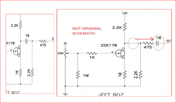
Quick question for those kind enough to read this. I see a lot of capacitor coupled circuits out there, and there isn't absolute consistency on where the cap is placed. I'm using this circuit as an example for my question - because of it's complexity 😀
Is there any harm or change in the operation if the coupling cap were moved to the final output? I'm thinking NO, but i'm probably missing the point as usual.
Attachments
Sheesh, I've been away too long. Thanks to this thread I was reminded I made one of these almost 10 years ago
Quick question for those kind enough to read this. I see a lot of capacitor coupled circuits out there, and there isn't absolute consistency on where the cap is placed. I'm using this circuit as an example for my question - because of it's complexity 😀
Is there any harm or change in the operation if the coupling cap were moved to the final output? I'm thinking NO, but i'm probably missing the point as usual.
IMHO The circuit will not operate the same. The capacitor, when positioned as in the original circuit in combination with the 2k2 resistor to ground , will eliminate pops when connecting or disconnecting the preamp. Also the 2k2 resistor to ground will affect the drain voltage if you reposition the cap as drawn.
Last edited:
- Home
- Amplifiers
- Pass Labs
- Jfet BOZ