hello, i make p2p jboz. it hum. input, drain resistor 620ohm, source resistor 10 ohm. value bad? also no output resistor 🙂 which making it hum?
Well, it's been couple of months since this thread has seen any action, so I'm here to bring it back to life (or kill it for good 😉 ).
I decided to put together a JBOZ, just for kicks. I breadboarded it using parts I had or that I could find at the surplus store. Followed NP's schem from page 1 w/o any modifications. Powered by two 9V batteries. JFETS are 2SK170s approx. 12mA Idss. For testing, input was iPhone and laptop. Output through an F5.
When playing music, more complex passages with a lot of instrumentation, drums, etc. sounded mushy and garbled. Less complex passages sounded fine.
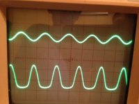
My son and I hooked the amp up to a scope, put some sine waves through it, and got the results shown in the attached photos. I'm new to using an oscilloscope, so correct me if I'm mis-interpreting the readings.
The first photo shows a 1kHz wave. Input (top trace) is ~0.1V (0.1v/div) and output (bottom trace) is ~4V (2v/div).
The second photo shows a 1kHz wave at clipping. Input (top trace) is ~0.25V (0.1v/div) and output (bottom trace) is ~12V (5v/div).
Obviously some weird distortion... What could be the cause?
Possibilities I can think of:
1) Bad/fake JFETs. Got them a while ago from what seemed like a reputable ebay seller (U.S., not Chinese).
2) Sub-par mylar caps. They may be very good caps; I don't know. I got them at the surplus store so they were cheap. I don't know enough to even know if "bad" caps can affect the signal as shown.
3) Bias too low? How to adjust?
Any other ideas?
Again, this is just for kicks. Seemed like a fun project for a beginner like me to learn a bit more...
I decided to put together a JBOZ, just for kicks. I breadboarded it using parts I had or that I could find at the surplus store. Followed NP's schem from page 1 w/o any modifications. Powered by two 9V batteries. JFETS are 2SK170s approx. 12mA Idss. For testing, input was iPhone and laptop. Output through an F5.
When playing music, more complex passages with a lot of instrumentation, drums, etc. sounded mushy and garbled. Less complex passages sounded fine.
My son and I hooked the amp up to a scope, put some sine waves through it, and got the results shown in the attached photos. I'm new to using an oscilloscope, so correct me if I'm mis-interpreting the readings.
The first photo shows a 1kHz wave. Input (top trace) is ~0.1V (0.1v/div) and output (bottom trace) is ~4V (2v/div).
The second photo shows a 1kHz wave at clipping. Input (top trace) is ~0.25V (0.1v/div) and output (bottom trace) is ~12V (5v/div).
Obviously some weird distortion... What could be the cause?
Possibilities I can think of:
1) Bad/fake JFETs. Got them a while ago from what seemed like a reputable ebay seller (U.S., not Chinese).
2) Sub-par mylar caps. They may be very good caps; I don't know. I got them at the surplus store so they were cheap. I don't know enough to even know if "bad" caps can affect the signal as shown.
3) Bias too low? How to adjust?
Any other ideas?
Again, this is just for kicks. Seemed like a fun project for a beginner like me to learn a bit more...
Attachments


Thanks. Is it normal for it to be clipping asymmetrically (bottom swing only) as seen in the first photo, at only 4V?
It's obvious it'll clip at 12V; I just added that picture in case it revealed some useable information for someone who knows this better than I do.
It's obvious it'll clip at 12V; I just added that picture in case it revealed some useable information for someone who knows this better than I do.
OK, Checked the drain voltage and it was .98V 😱
Changed drain R to 1K and got 7.8V; much better. Looking through my paltry supply of resistors for something that'll bring it closer to 9V...
Changed drain R to 1K and got 7.8V; much better. Looking through my paltry supply of resistors for something that'll bring it closer to 9V...
Annnnnnnnnd... Success! 😀
Paired an 82K resistor with the 1K to get a drain voltage of 8.6V.
Sounds beautiful...
Paired an 82K resistor with the 1K to get a drain voltage of 8.6V.
Sounds beautiful...
Single Ended amplifiers start generating substantial second harmonic as the output voltage rises.Thanks. Is it normal for it to be clipping asymmetrically (bottom swing only) as seen in the first photo, at only 4V?
It's obvious it'll clip at 12V; I just added that picture in case it revealed some useable information for someone who knows this better than I do.
It becomes gross at about half the maximum output voltage.
+-9Vdc gives a 18V supply and a SE can give ~6Vac into a very high load resistance.
Above 3Vac the 2nd will be gross.
Aim for a maximum signal into a very high load resistance of around 2Vac (on +-9Vdc) and depending on bias current quite a bit less when loaded with typical load impedances.
2Vac is 6Vpp. That should "look" like a reasonable sinewave.
2Vac is also the output of many digital sources.
A Buffer (1 times gain) is at it's sensible limit trying to pass a digital derived 2Vac using two 9V batteries.
Last edited:
This is exactly why a Jfet BOZ will perform substantially better with a buffer stage after.
They also work better with a negative rail so that you can push reasonable output voltage and bias current through the first stage without hitting the rail prematurely.
Remember that the BOZ was always an exercise in minimalism rather than fidelity, it can be easily improved upon.
Shoog
They also work better with a negative rail so that you can push reasonable output voltage and bias current through the first stage without hitting the rail prematurely.
Remember that the BOZ was always an exercise in minimalism rather than fidelity, it can be easily improved upon.
Shoog
OK, so now I'm thinking of putting JBOZ together with a phono stage, probably Le Pacific, in the same housing. I'd like to run them off a single 24V DC notebook power supply (I know, batteries are easier/better; I just don't like using them). A few questions:
1) Am I tempting the noise demons by putting these together in a (small) enclosure? The chassis will be primarily copper, and I can separate the JBOZ board from the phono board with a copper partition.
2) Can someone suggest a power distribution scheme to get 18V to JBOZ and 24V to phono pre? Obviously a voltage regulator for JBOZ, but what sort of filtering?
3) Does is make any difference if the phono stage is switched, so that it is only powered up when phono is selected as input?
Anything else I'm missing?
Go dual chassis: power supplies and circuits.
Raw DC would be a few volts over 24v and uses adjustable regulators for 18v and 24v.
Keep raw DC capacitance under 10k uF.
Raw DC would be a few volts over 24v and uses adjustable regulators for 18v and 24v.
Keep raw DC capacitance under 10k uF.
<snip>
Keep raw DC capacitance under 10k uF.
Any particular reason why?
Jan Didden said it can cause noise or distortions in the power supply. See super reg threads. I used more than 10k uF in my pearl II and ba3-pre. Will reduce at some point.
I have observed laptop supplies kicking into protect mode with too high capacitance as well, presumably from the incoming surge to fill them up.
I have had and used both these circuits. They both did not like smps power supplies. The jfet boz was noisy and the boozehound seriously suffered in sq. I resorted to batteries for both.
Might be different with another reg before the preamp. But these are both simple circuits that are pretty sensitive to supply quality.
Might be different with another reg before the preamp. But these are both simple circuits that are pretty sensitive to supply quality.
Can someone please explain to me what makes this circuit unique? I don't mean to diminish Mr. Pass' efforts; this is an excellent sounding pre, but isn't this basically just a standard common source JFET amp? The general circuit is pretty much identical to what I see in my text books for this type of amplifier so is it the values of the resistors which make this design unique?
It's not a commercial preamp from Nelson or even something that he self proclaimed as original. I believe someone here at diyaudio commented on a simple preamp with gain (I think it started in the B1 thread) and Nelson published a schematic for the jfet boz as an idea or something to try.
- Home
- Amplifiers
- Pass Labs
- Jfet BOZ