Thanks muzzmastah...
I tried a 100k and a 10k right off the RCA input today. I like the 10K, 'been listening to that a couple of hours. I'll try a similar arrangement to the schematic you've posted and see if it's better!
By the way, I also tried some polyprope 10uF caps today and they do sound better than the polyester and different than the PIOs. It is a fun design to play with...frustrating and fun. I'll post results soon.
I did try the shunt style and simple resistor style, they are only subtly different. I ended up liking 5k simple resistor the best.
I also went back and built a regular BOZ very carefully and from premium parts. JBOZ is cleaner, clearer but you know that BOZ has something going on too. BOZ is a bit rounder and well balanced for its lack of clarion voice.
Now, how do I get both qualities at once...SOBOZ?
I also went back and built a regular BOZ very carefully and from premium parts. JBOZ is cleaner, clearer but you know that BOZ has something going on too. BOZ is a bit rounder and well balanced for its lack of clarion voice.
Now, how do I get both qualities at once...SOBOZ?
OK, I have experience w/a JBOZ running off 12 AA batteries. Matched Jfets, Clarity Cap SA caps. The sound...very good. Lot's of drive and dynamics. I loved it.
I recently built a BA-3 with the same output caps and a regulated 317/337 power supply.
The BA-3 shares the same basic tonality but is far more refined. Better balance, especially in the low end and overall it sounds more relaxed, controlled, refined and smoother. It is not as raw and sounds wider and more detailed. But I would best describe it as being more balanced and controlled. It's like going from a muscle car to a modern sports car. Each has it's charms, both are fast but the modern car is much more refined and pleasant to live with.
The JBOZ is a simple design (simple can be good) but sounds like it when compared to the BA-3. Both are good, but I doubt anyone would would prefer the JBOZ. That being said we are talking the difference between "really good" and "great". There is always something better...
J310 Jboz
Hey all,
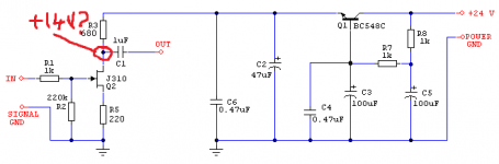
I just put together a version of the attached circuit (thanks for the schematic and values juma!). I deliberately picked j310's with a 35mA Idss (to match juma's original build) and I've found that the node between the drain resistor and the jfet is sitting at about 20V when run off a 24V supply.
Now correct me if I'm wrong, but wouldn't we be wanting about 14V or so there? My understanding was that the aim is to have that node sitting at about 1/2 the supply voltage plus a little bit? Node indicated on the schematic...
...and now I might just nervously check my circuit to ensure I haven't made an *** of anything.
... and to clarify the post I started from http://www.diyaudio.com/forums/pass-labs/103050-jfet-boz-75.html#post1832806
Hey all,
I just put together a version of the attached circuit (thanks for the schematic and values juma!). I deliberately picked j310's with a 35mA Idss (to match juma's original build) and I've found that the node between the drain resistor and the jfet is sitting at about 20V when run off a 24V supply.
Now correct me if I'm wrong, but wouldn't we be wanting about 14V or so there? My understanding was that the aim is to have that node sitting at about 1/2 the supply voltage plus a little bit? Node indicated on the schematic...
...and now I might just nervously check my circuit to ensure I haven't made an *** of anything.
... and to clarify the post I started from http://www.diyaudio.com/forums/pass-labs/103050-jfet-boz-75.html#post1832806
Attachments
Last edited:
Hi aspringv,
what is the voltage across the R5 - you should have more than 2V there (if not, check the orientation of Q2 and the value of R5, also the value of R3) ?
And while you are at it, check everything else once more... 🙂
what is the voltage across the R5 - you should have more than 2V there (if not, check the orientation of Q2 and the value of R5, also the value of R3) ?
And while you are at it, check everything else once more... 🙂
Hi Juma; thanks for repling!
R5 shows 1.75V approximately. R7 showing 5.35V (approx 8mA, so a bit lower than the projected 10mA)
I'm checking the j310 just now and as best I can see she's connected the right way around...
I guess I must of measured the Idss incorrectly originally (or I wrote it down incorrectly)... I think I have the other two i popped in that bag floating around on my desk here somewhere to test and check.
Anywho, I suppose the way forward is to decrease the value of the source resistor to get the target 2V drop, and then tweak the drain resistor to get the target voltage?
Edit: or even start reading properly about load line optimization
Last edited:
... I suppose the way forward is to decrease the value of the source resistor to get the target 2V drop, and then tweak the drain resistor to get the target voltage?...
You got it

The idea is to pick the value of R5 that will give you about 10-15mA through JFET and then choose the R3 that will put the JFET's drain at about half of voltage present at Q1's emitter.
... I dropped a 120R in in place of the original R5 value of 220R and the end result is a bias of about 12mA. This gives a drop of 8V over the existing 680R value at R3. I think I may just bump the bias up instead of increasing R3...
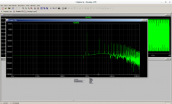
Sorry to resurrect this old thread, but I am attempting to design a SS version of the Super Linear Cathode Follower. Basically this has a JFetBOZ at the front end. In my simulations using LTspice I am getting horrendous third harmonic figure. The degenerative feedback on the 2SK170 source is knocking back the 2nds harmonic but having almost no effect on the higher order harmonics.
Is what I am measuring the reality with simple JFET amplifiers such as the JBOZ ?
Shoog
Is what I am measuring the reality with simple JFET amplifiers such as the JBOZ ?
Shoog
Attachments
Its so simple theres no need to zip.
The cathode follow works perfectly adding almost no distortion, but the front end generates the distortion profile I posted as tested at the drain of the JFET.
Nothing I try reduces the higher order harmonics below what I showed and I tried about three different models at this stage.
Shoog
The cathode follow works perfectly adding almost no distortion, but the front end generates the distortion profile I posted as tested at the drain of the JFET.
Nothing I try reduces the higher order harmonics below what I showed and I tried about three different models at this stage.
Shoog
Attachments
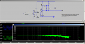
That model wasn't working for me. Delete the .inc statement and the simple .model works adequately by itself and is in the .asc file.
Shoog
Shoog
Can I ask, the circuit looks fundamentally the same regarding the components surrounding the 2SK170 so is its just the simulation run parameters you have changed to get the better result and accuracy ?
The FFT plot now looks much more acceptable and now looks worth building.
As you can probably tell - I am still new to ltspice and have considerable amounts to learn to get really useful results.
Shoog
The FFT plot now looks much more acceptable and now looks worth building.
As you can probably tell - I am still new to ltspice and have considerable amounts to learn to get really useful results.
Shoog
parameters are what's important , but not less than models
you have LT Spice group at Yahoo , same as few tutorials floating here
disclaimer - not that I invest any substantial time in those ....... due to my chronic lack of time , I'm more hit or miss type
you have LT Spice group at Yahoo , same as few tutorials floating here
disclaimer - not that I invest any substantial time in those ....... due to my chronic lack of time , I'm more hit or miss type
parameters are what's important , but not less than models
you have LT Spice group at Yahoo , same as few tutorials floating here
disclaimer - not that I invest any substantial time in those ....... due to my chronic lack of time , I'm more hit or miss type
Thanks for the help.
Shoog
If I may ask - was the solution in the param settings, the model, or something I'm not clever enough to work out?
second question - I see you noted a Beta parameter change. I have no idea how to alter a jfet model to a different idss/Vp setting. is that the solution?
second question - I see you noted a Beta parameter change. I have no idea how to alter a jfet model to a different idss/Vp setting. is that the solution?
- Home
- Amplifiers
- Pass Labs
- Jfet BOZ