Thanks Mr. Pass.
it would definately help. I would be able to leave
the channel level on my AVR to 0dB. currently
it's up at +3dB including the 10dB gain of the Jboz.
I built a battery proto versions. sounds great so far.
just amazing for a single fet. I have inefficient but great sounding maggies. 😀
at 2K and 24V the distortion is dramatically reduced?
does the input level affect the distortion? for ex. you
said maybe .3%, it would be .3% regardless if the input level
is 500mVrms vs. 1.25Vrms?
most likely I would never turn the volume to max to reach 1.25Vrms.
also curious, what level THD can the typical human ear perceive the distortion?
Mr. Pass,
How about 2.49K and +28V?
1.23Vrms (in) and 5.32Vrms (out)
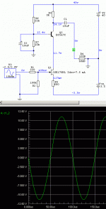
I found a sim distortion anaylzer I put on the output of the fet.
Distortion Anazlyzer-XDA1:
Fundamental Freq. set to 1KHz
Resolution Freq. set to 100Hz
Displays THD of 0.355% (this sim backs up your supercomputer brain of yours )
I varied the resistance from original 2K & 24V
to 2.49K & 28V or 2.94K & 30V. the distortion is still at around
0.3%
I tried your original circuit(2.2K & 35V), since it clips, I use 50mVp
on the input. Distortion says 1.355%.
thank you.
How about 2.49K and +28V?
1.23Vrms (in) and 5.32Vrms (out)
I found a sim distortion anaylzer I put on the output of the fet.
Distortion Anazlyzer-XDA1:
Fundamental Freq. set to 1KHz
Resolution Freq. set to 100Hz
Displays THD of 0.355% (this sim backs up your supercomputer brain of yours )

I varied the resistance from original 2K & 24V
to 2.49K & 28V or 2.94K & 30V. the distortion is still at around
0.3%
I tried your original circuit(2.2K & 35V), since it clips, I use 50mVp
on the input. Distortion says 1.355%.
thank you.
There are simply limits as to what a part will do. You can reduce
the current variation by raising the load resistance for a given
output voltage, but your output impedance will go up proportionally.
Also, you will have to cascode the part to reduce distortion associated
with gain variations due to the AC component of Vds.
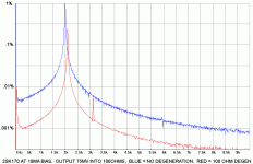
Here is a typical spectral curve:
the current variation by raising the load resistance for a given
output voltage, but your output impedance will go up proportionally.
Also, you will have to cascode the part to reduce distortion associated
with gain variations due to the AC component of Vds.
Here is a typical spectral curve:
Attachments
It would be the 3K resistor.
You can put any kind of "bleeder" resistor after the cap - the intent is
to prevent big thumps when something is connected to the output and
the cap starts to charge.
😎
You can put any kind of "bleeder" resistor after the cap - the intent is
to prevent big thumps when something is connected to the output and
the cap starts to charge.
😎
You can put any kind of "bleeder" resistor after the cap - the intent is
Thank you Mr. Pass.
This cascode circuit shows THD of .105% for 1.24Vrms in,
about 11.48dB gain. Does that THD sound right?
Is .1% considered still too high?
I will try this circuit with my proto once I order some of those
BC547C's.
from this lesson, I see the gain has nothing to do with
the voltage swing. Both are about 12dB. One has voltage
swing of 10Vpp and the other about 5Vpp. What is
the advantage of a greater voltage swing? better dynamics?
You can put any kind of "bleeder" resistor after the cap - the intent is
the 47k is my load. if I put a 820k resistor after the cap to ground,
does that change the impedance to 820k? or it's still 3k?
sorry, I'm unclear on this.
thanks
Bengali said:This cascode circuit shows THD of .105% for 1.24Vrms in,
about 11.48dB gain. Does that THD sound right?
Is .1% considered still too high?
That would be 5 volts rms out at .1%, and the original BOZ
was .2% at 5 volts. I would call that an improvement.
Bengali said:the 47k is my load. if I put a 820k resistor after the cap to ground,
does that change the impedance to 820k? or it's still 3k?
The resistor to ground would be in parallel with the 3K to form the
output impedance, so it would then be 3000*820000 / (3000+820000)
or slightly less than 3K.
😎
That would be 5 volts rms out at .1%, and the original BOZ. and the original BOZ was .2% at 5 volts. I would call that an improvement.
I was not clear. I meant the circuit I was working on that had .3% THD. yes, definately much better.
The resistor to ground would be in parallel with the 3K to form the output impedance, so it would then be 3000*820000 / (3000+820000) or slightly less than 3K.
ah, the light has turned on 🙂
Thank you. 😀
Mr. Pass,
aside from LM337 for -3.5V. do you have something simple
yet better than the LM317/337? or some circuit after the V.R.'s to improve noise issues for these jfets?
Thank you.
aside from LM337 for -3.5V. do you have something simple
yet better than the LM317/337? or some circuit after the V.R.'s to improve noise issues for these jfets?
Thank you.
Nothing special. Usually I don't worry too much about tight voltage
regulation on supply, and I use RC networks after regulators to
passively lower noise and/or reduce dynamic impedance.
😎
regulation on supply, and I use RC networks after regulators to
passively lower noise and/or reduce dynamic impedance.
😎
I was asking a highly experienced EE about this cascode circuit, to improve noise,protection,etc... It's interesting EE vs. Audio EE has way different mind set, as if audio guys are nuts. I get feedback like WHY would you do that??? 😀
this is what was said on the matter:
{Not exactly sure why you chose a cascode circuit with the FET as the linear element. For a 5.6 v pk to pk signal you might be better served with a bipolar device. Check the IV curves for eveness in the steps as a function of ib or Vgs for the two device types. Also if you are looking for linearity you really need to close the loop on this with some feedback.}
I was hoping to get a little more clarity on the close loop and feedback vs. this open loop implementation, for learning purposes.
thanks.
Attachments
It wouldn't be much work to build it both ways.
Why don't you try it and see?
You certainly would learn much more than you can get by
soliciting an opinion.
😎
Why don't you try it and see?
You certainly would learn much more than you can get by
soliciting an opinion.
😎
Nelson Pass said:It wouldn't be much work to build it both ways.
Why don't you try it and see?
You certainly would learn much more than you can get by
soliciting an opinion.
😎
So true. Sometimes I feel like a boy learning to ride a bike; Nelson's there to help me maintain balance. 🙂
many different ways to learn, it's sometimes hard trying to ask the right question hence the post of another's opinion. 
trying a different circuit right now 😀

trying a different circuit right now 😀
I understand completely. It's even harder, as a student of the art, to submit an idea, knowing full well that it's probably going to get less petting and more kicking. 😉 😀
juma said:Following the advice from reverend Zen Mod 😉 three months ago I tried J310/JBOZ as a preamp for F5. The results were very good. They were posted and discussed on a local Serbian forum. Id was 10-11 mA. J310 were from ON Semiconductors (Idss 35 mA). Preamp's gain was 2.1 V/V
Here is the schematic:
Hi, I am thinking about trying the j310 too. The 2sk170 circuit I am using now sounds mighty find, but I curious if the j310 can be better.
On the 2sk170, I now have 18.5V and -2.95v with Rd=1.2k and Rs=430R. Vd=9.7V and Vs=58mV.
Since the j310 has a much higher Idss, is there any disadvantage using a high Id like 15mA to 20mA?
Eg, 18.5V & -2.95V with Id=15mA, I can use Rs=200 and Rd around 600.
Nelson Pass said:I think you should try it.
😎
Ok, from The Man, I guess that is a good enough reason to try.
Has anyone here go crazy and try Id above 30mA
😱
- Home
- Amplifiers
- Pass Labs
- Jfet BOZ


