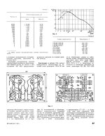
fh = 20kHz

We can completely ignore the mechanical part of the stylus.
With your generator impedance model, a real load of approx. 8k8Ohm results in a cut-off frequency of exactly 20kHz. My God, Nick S. doesn't even load the generator with 150k!
😱
The connection between the left side of our selective amplifier ( RIAA-EQ) and the last Zero incorporated by Nick S. is something I can't understand, even with two engineering degrees.
Dear Hans,
I think you've lost your way here.
Best regards,
HBt.
My intention was to leave this thread, but when quoted completely wrong, this has to be corrected
@hbtaudio, you obviously haven't read the paper that I posted correctly.
1) I did not use a 33 1/3 LP but a 45rpm from CH Precision, see Fig 2 in my paper.
2) The sweep was not linear, they never are, but exponentially, resulting in a -10dB/dec slope as shown with the black line in Fig 1.
The 17dB/dec that you mention is simply bad measurement from your side.
3) The replacement of the Generator's part that you show, belongs to a a relatively a-typical MM Cart, the Audio Technica AT22 having a very low inductance, you should have mentioned that Model for completeness and it's circuit was based on the VNA impedance measurement below.

When you had taken the time to look at Fig 4 in the paper, you would have seen that especially it's beryllium cantilever has a flat response up to 20Khz so for this Generator with a very large BW, the Cantilever assembly will be the BW limiting factor

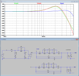
The FR from complete system in Blue and Generator alone in red is in the image below, resp out1 and out2.

In Posting #41 you can see the FR with 150K//25pF + 7usec Neumann zero, but also with 150K//25pF and 47K//100pF
To conclude:
When you only halfway understand parts of the information, it's almost malicious to claim that someone has lost his way.
Hans
@hbtaudio, you obviously haven't read the paper that I posted correctly.
1) I did not use a 33 1/3 LP but a 45rpm from CH Precision, see Fig 2 in my paper.
2) The sweep was not linear, they never are, but exponentially, resulting in a -10dB/dec slope as shown with the black line in Fig 1.
The 17dB/dec that you mention is simply bad measurement from your side.
3) The replacement of the Generator's part that you show, belongs to a a relatively a-typical MM Cart, the Audio Technica AT22 having a very low inductance, you should have mentioned that Model for completeness and it's circuit was based on the VNA impedance measurement below.
When you had taken the time to look at Fig 4 in the paper, you would have seen that especially it's beryllium cantilever has a flat response up to 20Khz so for this Generator with a very large BW, the Cantilever assembly will be the BW limiting factor
The FR from complete system in Blue and Generator alone in red is in the image below, resp out1 and out2.
In Posting #41 you can see the FR with 150K//25pF + 7usec Neumann zero, but also with 150K//25pF and 47K//100pF
To conclude:
When you only halfway understand parts of the information, it's almost malicious to claim that someone has lost his way.
Hans
Last edited:
I can assure you that I fully understand your field of work - is that enough of an announcement?(...) To conclude:
When you only halfway understand parts of the information, it's almost malicious to claim that someone has lost his way.
Hans
Can we please put this topic (your topic) to rest.
hbt.audio
#
continue with Nick's equalizer here ...
Attachments
This is also a truism and unfortunately always the case.BW, the Cantilever assembly will be the BW limiting factor
I miss the relevance - especially in Nick's thread. As well as the correlation with Nick's H(jOmega) ..! The question is not what I would like, but what you would like to tell us readers.
kindly,
HBt.
No you don't, and I will further show below .I can assure you that I fully understand your field of work - is that enough of an announcement?
Yes of course, but then please stop telling chaos.Can we please put this topic (your topic) to rest.
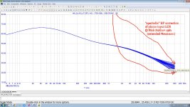
That the Generator has always a larger BW as the Cantilever is almost never the case as is shown in the image below for a more usual Cart the Audio Technica AT150 with Lcart 360mH and Rcart 665R, terminated with 47K//100pF.This is also a truism and unfortunately always the case.
See the Generator's FR in blue having a narrower BW as the Cantilever's FR in green.
Overall FR in red shows the result of combining both responses.
And here you see exactly what Nick tries to achieve, changing the red 40dB/dec into a 20dB/dec by using a higher impedance for the Generator, thereby shifting it's -3dB point with 150K//25pF.
Now the Cantilever's response becomes dominant while now also having a 20dB/dec slope.
Point is that when also adding an additional 7usec zero, the FR at 30Khz will get a huge lift as shown in #41.
Hans
Attachments
yes if use old heavy effective tip (>= 1 mg) mass cartridge (from 70s of last century)try 82k...100k//47pF
Last edited:
This means that I like both Hans and Marcel models, but they are not really interesting for me. Because modern cartridges with a reduced needle mass below 0.25 mg do not manifest any noticeable mechanical resonance in the audio range, when used with adequate low capacitance input phono preamp (even budget ones, like here https://www.diyaudio.com/community/...mp-with-tube-thd-spectrum.422889/post-7920790 ). And what can be detected in the deviation of their frequency response from the ideal is easily corrected in my phono preamplifier by selecting one resistor R18, and even then only for some atypical cartridges.What do you mean by that?
Attachments

Last edited:

O.k. Nick,I like both Hans and Marcel models, but they are not really interesting for me. Because modern cartridges with a reduced needle mass below 0.25 mg do not manifest any noticeable mechanical resonance in the audio range, when used with adequate low capacitance input phono preamp (even budget ones,
I’m happy to see that at last a real discussion seems to start.
One comment is that I think to have proven that the cantilever assembly is unaffected of what termination will be used, but I agree that the lower the tip mass, the higher the mechanical resonance frequency and if so it makes sense to extent the Generators FR by changing the termination.
fr = (0.632/πSqrt(m)*(E0²FvR)^1/6
With m the equivalent tip mass.
Eo the Young modulus, 3.76e9 N/m² for vinyl
Fv the the stylus force, usually 2 gram
R is the tip radius touching the track wall.
So fr goes up with 1/SQRT(tip mass).
I have no idea what tip masses are from the Carts that I investigated, it's worth trying to find them.
One last thing, I don't understand what your first attachment is telling about aperiodic input LCR , maybe you can give a short explanation in English.
Hans
So fr goes up with 1/SQRT(tip mass).
I have no idea what tip masses are from the Carts that I investigated, it's worth trying to find them.
Yes, 1/SQRT(tip mass) ! And this means that a cartridge with a mass of 1 mg (Ortofon SPU from the 1960s) has a mechanical resonance of approximately 20 kHz, while modern semi-budget cartridges with a mass of 0.25 mg have already flown away with a mechanical resonance above 40 kHz, and top modern cartridges with a mass of 0.06 mg (Technics EPC-P100CMK4 (MM, boron pipe, 0.2x0.7mil)) - generally above 70 kHz. [ to find it see
https://www.patreon.com/posts/pravda-pro-massu-93731535 ]
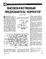
I meant that any standard input LCR circuit above the resonance frequency is a second-order LPF with a 12 dB/octave roll-off, and additionally - a fairly steep phase response. In my phonopreamp back in 1981 (Radio #3\1981 p.35-37 - see here https://www.patreon.com/posts/kak-korrektsiia-121482395 or attached files in russian ), I minimized the input capacitance to 26 pF, while the input circuit turned into a "cartridge inductance / input resistance" LR chain, which is a first-order LPF with a 6 dB/octave roll-off and a smooth phase response. I corrected the frequency response roll-off from this first-order filter by inserting one resistor into the 75 µs RIAA correction circuit (R18 in my modern Cy-XXI or R13 in 1981), calling it aperiaodic (now I can call it "extended Neumann" 🙂 ) , to emphasize the removal of the resonant input circuit. And I had a flat responce in my MM in 1981, when most fall in 16 kHz.One last thing, I don't understand what your first attachment is telling about aperiodic input LCR , maybe you can give a short explanation in English.
Attachments
Last edited:
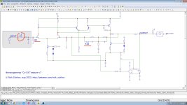
This is Nick's contribution to the resulting amplitude-frequency response.

Hans very own pickup model is completely left out.
I am pleased that the boost used by Nick is solely an optional equalization to equalize the high frequency range of the low-budget MM. A great idea. And I have often also implemented the 20Hz IEC recommendation myself.
We can discuss Hans' pickup model elsewhere when Bob Cordell is back.
Thank you very much Nick,
but please don't name the part that can be specially adapted (to the pickup) after “Neumann” - this leads to unnecessary confusion and disputes.
😎
Great work,
HBt.
but please don't name the part that can be specially adapted (to the pickup) after “Neumann” - this leads to unnecessary confusion and disputes.
😎
Great work,
HBt.
O.K thx for your explanation, I appreciate that we are getting a nice step forward.Yes, 1/SQRT(tip mass) ! And this means that a cartridge with a mass of 1 mg (Ortofon SPU from the 1960s) has a mechanical resonance of approximately 20 kHz, while modern semi-budget cartridges with a mass of 0.25 mg have already flown away with a mechanical resonance above 40 kHz, and top modern cartridges with a mass of 0.06 mg (Technics EPC-P100CMK4 (MM, boron pipe, 0.2x0.7mil)) - generally above 70 kHz. [ to find it see
https://www.patreon.com/posts/pravda-pro-massu-93731535 ]
I meant that any standard input LCR circuit above the resonance frequency is a second-order LPF with a 12 dB/octave roll-off, and additionally - a fairly steep phase response. In my phonopreamp back in 1981 (Radio #3\1981 p.35-37 - see here https://www.patreon.com/posts/kak-korrektsiia-121482395 or attached files in russian ), I minimized the input capacitance to 26 pF, while the input circuit turned into a "cartridge inductance / input resistance" LR chain, which is a first-order LPF with a 6 dB/octave roll-off and a smooth phase response. I corrected the frequency response roll-off from this first-order filter by inserting one resistor into the 75 µs RIAA correction circuit (R18 in my modern Cy-XXI or R13 in 1981), calling it aperiaodic (now I can call it "extended Neumann" 🙂 ) , to emphasize the removal of the resonant input circuit. And I had a flat responce in my MM in 1981, when most fall in 16 kHz.
I tried to find the tip masses for the Carts that I investigated, but without success so far, so maybe they are "heavy".
Apart from the fabulous Technics 205 series, I was not aware that modern MM's have such low tip masses as 0.25mg.
So to resume: your solution is optimal for Carts having a very low tip mass, having a mechanical resonance way beyond the 20Khz.
By changing the Generator's dominant BW with 47K//150pF to 150K//25PpF instead, you will get
an overall extended BW beyond 20Khz.
So far so good.
In such cases where both mechanical and electrical BW's are flat to beyond 20Khz, an "extended 7usec Neuman" has no function but can be discarded by making R108's value zero ohm.
For carts with a higher tip mass with consequently a lower BW, a logical way to extend this BW seems to use a an extra zero at 7usec, but with the samples in #41 this didn't work out as well as compared to not applying the 7usec zero but tuning the 25pF cap instead.
But this a free choice that anybody can make for himself, and because most of he effect is in the supersonic area, the differences may not even be audible.
A MM Cart is a complex machine, where "one solution fits all" seems hard to find.
To get the flattest possible FR, some tuning always helps to get an optimum.
And that's exactly where an MC shines, it's Generator BW is very far away in the supersonic area and it's low tip mass is also a guarantee for a flat response to way above 20Khz.
But unfortunately this comes at a price penalty.
Hans
In my schematic, the corrective eq resistor in question is called R5, so please don't be surprised.

A tactile sensor is anything (else) but a complex structure.A MM Cart is a complex machine, where "one solution fits all" seems hard to find.
It is the most primitive structure in the world and is extremely easy to model.
You are concerned with the electrical termination, i.e. the input impedance of the measuring amplifier - or our RIAA-Pre.
This bone has been eaten away.
kindly,
HBt.
You are wrong again.Hans model of the mechanically moving part shows that there must be an upper mechanical limit reflected on the electrical side. f_limit < 25kHz.
Well, that's a truism and the pickup manufacturers usually specify this limit as well. In my above example of the AT420E, AT says 25kHz is the upper limit. And exactly in this range the termination with 47kOhm || 150pF is exactly correct, i.e. if you look at the (let's say incorrectly "Bode") Bode diagram between 10kHz and 30kHz, everything is totally correct quantitatively. Multiplication with the mechanical transfer function is now welcome.
Posting #43 illustrates exactly what it is supposed to illustrate.
Depending on component values, with this generic model you can get any frequency limit you want as well for the mechanical as for the electrical part.
That does not mean that an LP can be cut to go beyond a certain limit.
My Benz LP goes to 50Khz +/- 0.1Hz and can be well fitted in this generic circuit diagram.
But this can only be measured with special disks.
O.K. have a nice day.A tactile sensor is anything (else) but a complex structure.
It is the most primitive structure in the world and is extremely easy to model.
Hans
You are wrong again.
when quoted completely wrong, this has to be corrected
is simply bad measurement from your side.
When you only halfway understand parts of the information,
No you don't, and I will further show
then please stop telling chaos.
Dear Mr. Polak,
this is your way of communicating - not mine.
Of course, everything here is directly dependent on the numerical values that someone enters.Depending on component values, with this generic model you can get any frequency limit you want as well for the mechanical as for the electrical part.
I can't see any substantial contribution from your side. I am sorry.
best regards,
HBt.
" Das wünsche ich Dir ebenfalls Hans."O.K. have a nice day.
Helge, either I ignore your postings or notify you when you are wrong.this is your way of communicating - not mine.
Tell me what you prefer.
All the best
Hans
I prefer methods of scientific work and measurement technology ...You prefer bones?
But none of this has anything to do with Nick Sukhov's Phonoentzerrer - with Nick's H(jOmega) or Bob's "VinylTrak".
my method: measure the frequency response on a test disk with your cartridge at least up to 27 kHz (using a test disk with a 20 kHz sweep but with playback not at 33.3 but 45 rpm), - if the frequency response at 20...25 kHz has a roll-off, then increase the resistance of R18, and if it has a hump, then decrease the resistance of R18. The result of changing the resistance of R18 is in the attachmentHave you developed a proven test routine that can tell right
Attachments

Last edited:
We won't argue with the price, but the MC has two more drawbacks - a non-replaceable stylus and the permanent soldering of four copper, albeit thin, but still rigid wires between the moving coils and the output contacts of the cartridge. As a result, the tracking force due to the real worse compliance of the MC ( >= 2.5 g) is more than that of most MM (1.5...2 g) cartridges.But unfortunately this comes at a price penalty.
- Status
- Not open for further replies.
- Home
- Source & Line
- Analogue Source
- JFE2140/OPA192 jFET/MOS phono preamp with "tube" THD spectrum