I think for MC too.And that is also absolutely correct, namely the best way for an MM system.
Attachments
Of course, something like this cannot be patented, but some form of product protection is certainly possible.Do you hold a patent for the 25pF/150kohm loading?
Can this even be patented?
You really shouldn't dwell on stories like this.
Nick S. has thrown a remarkable phono EQ into the race. So I'm happy about this inspiration. For me, this is an enrichment.
kindly,
HBt.

@Nick Sukhov, It all depends on the contracts with the publisher.
AudioXpress has published an article from me in their december issue where I can freely send links to this article 3 month after publication.
But until then my hands ate tied.
Hans
AudioXpress has published an article from me in their december issue where I can freely send links to this article 3 month after publication.
But until then my hands ate tied.
Hans
All my patents on vinyl and tapes were in last century paralleled with Dolby [ https://en.wikipedia.org/wiki/Adaptive_biasing ] ;-) . In XXI I hold two patents on ABBA class power amps with dedicated Gm doubling compensation [ https://photos.app.goo.gl/BYLzUAfQeEioLnYW9 ] [ https://photos.app.goo.gl/8WYmVGsqa8jaPXLA9 ] [ https://photos.app.goo.gl/WBPRU9zGhXZ5k3Rr5 ]Do you hold a patent for the 25pF/150kohm loading?
Last edited:
When trying to play a video I get the message “For Members Only” !!!!!I do not understand how he can holds copyright of your circuit diagram . In almost 20 years of my tenure as editor-in-chief of Radiohobby magazine [ https://www.youtube.com/playlist?list=PLu1Wtw8bW_xjWNlh8FoJh7mfw3hRWOYYY ] , I have never appropriated the rights to other people's designs.
Hans
Some issues are for members only. But >70% are free, see for exampleWhen trying to play a video I get the message “For Members Only” !!!!!
Nick,
Now that we have cleared the confusion about "passive cooling" my second question was whether you added an extra zero to your Riaa network.
When changing the load from 47K//200pF to 150K//25pF, the difference between the two slopes beyond 20Khz are expected to be 20dB/dec since you shifted the Cart's Generator -3dB point at least a factor 2 to 3 to beyond 60Khz.
But looking at the spectra you showed in your video, the difference between the two slopes seems much larger as the expected 20dB/dec.
That's why I suspect that you added an extra (von Neumann) zero in the Riaa network.
Without adding any zero, a 30Khz sweep could be perfectly recorded as shown below.
So, when you added a zero, I wonder why ?
Hans
@Hans Polak
look here
But I don't want to reignite any old arguments, hopefully we are all relaxed and open enough.
look here
But I don't want to reignite any old arguments, hopefully we are all relaxed and open enough.
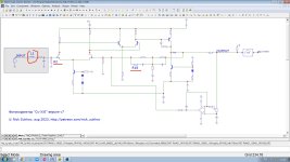
@hbtaudio, thx for pointing to a circuit diagram.
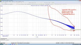
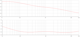
When the network below between the right Fet input and the output is what Nick is using, there is indeed an extra (von Neumann) zero at 7usec, explaining the much larger slope difference between 47K//200pF and 150K//25pF.
In this case it is a difference 40dB/dec that would be 20dB/dec without this added 7usec zero.
See in red the deviation from Riaa.
Hans
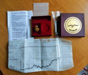
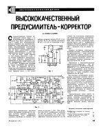
everything is more obvious than with the "Neumann pole". In 1980 I started experiments with a reduced input capacitance of the phono preamplifier and then discovered that when minimizing C, the inductance of the cartridge L forms, together with the input resistor, a first-order low-pass filter that rolls off higher frequencies with 6 dB\oct. To compensate for this roll-off, I used an additional resistor (R13 in 1981 picture and R18 in Cy-XXI_v7) in series with the capacitor of the 75-microsecond RIAA circiut. As a result, the frequency response became flat up to the highest conceivable for cartridges of the 80s (Shure M95ED) 30 kHz. Instead of the standard at that time roll-off of 12 dB/octave starting from 16...18 kHz with a standard input of 47 k/250 pF. Attached are files of my 1981 article, and modern MC12 simulation data.But I don't want to reignite any old arguments, hopefully we are all relaxed and open enough.
Attachments
For the metrological proof, you would have had to have a test record at the time, which would have had to have test tones up to, say, 2 times fh, i.e. up to 60kHz.As a result, the frequency response became flat up to the highest conceivable for cartridges of the 80s (Shure M95ED) 30 kHz. Instead of the standard at that time roll-off of 12 dB/octave starting from 16...18 kHz with a standard input of 47 k/250 pF.
fh -> 30kHz
(with normal RIAA, without 50kHz zero and also no IEC-20Hz recommendation as the simplest rumble filter)
Attachments
a first-order low-pass filter that rolls off higher frequencies with 6 dB\oct. To compensate for this roll-off, I used an additional resistor (R13 in 1981 picture and R18
- are -20dB per frequency decade
- with the cut-off frequency shifted upwards by -3dB to approx. 30kHz
Let's now assume that the slope falls ideally with -20dB to infinity, then you now want to cancel this fall within the complex negative feedback by counteracting it from fh (here around 30kHz) with +20dB per decade - or by using a zero there.
You have certainly not provided any direct metrological proof that the SHURE MM with 150kOhm and just under 25pF forms a TP1 with fh = 30kHz. This is only possible with the corresponding test oscillations on a specially cut record. And a clean RIAA EQ with only one zero at 318µs.
#
As long as the RIAA recommendation for EQ is fulfilled within the limits of 30Hz to 15kHz, or better still from 20Hz to 20kHz. That's all right - what counts in the end is the sonic result and the practicality of our circuit designs. And, at best, absolute freedom from noise.
Personally, I like to try out Nick's equalizer.
+1 Error
( |Zfb| + |Zn| ) / |Zn|
=
( |Zfb| / |Zn| ) + ( |Zn| / |Zn| )
=
|Zfb| / |Zn| +1
Our 75µs pole can no longer fall to infinity at around -20dB per decade; this actual 1st order low-pass filter may already end its descent in the audio frequency range. In other words: a non-inverting amplifier circuit can only amplify the signal, not attenuate it. However, the transfer function to be reset also requires attenuation ... i.e. |H(jOmega)| or S must become less than 1 at some point ... +1 can never ..!
This is the "+1 error", which can be completely corrected by an additional passive RC low-pass filter. This disturbance, also known as the fourth time constant, can be calculated precisely using network theory. For all known topologies.
However, deduction is sufficient, as are bode diagrams, a pencil and ruler, or a good simulation program.
There are no secrets!
HBt.
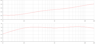
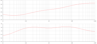
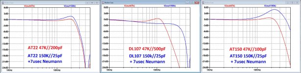
Nick, as the proof of the pudding I have simulated your circuit for three totally different Carts:
An Audio Technica At22 having a relatively low inductance for an MM Cart, a Denon DL107 which is a very robust Cart as sometimes used in Discos and another Audio Technica AT150 that needs a relatively low capacitive loading.
I have made two series, as shown in both images below.
1) one with the usual 47K with the proper termination capacitance for getting an optimal FR, but with no Neumann correction.
For the same Carts now with 150K//25pF + a 7usec Neumann zero.
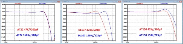
2) Again the same with 47K termination as under 1) as a reference
But now for the same Carts 150K without the Neumann zero but now with a properly selected Capacitance for an optimal FR.
The Images show that further tuning the 25pF cap to an optimal value and discarding the 7usec Neumann pole leads to better results for all totally different situations.
In fact this is no different to 47K terminating, where you also have to carefully tune the total termination capacitance.
The advantage for having the preamp into the TT is having a better protection against EMI.
Hans
P.S. With termination capacity is meant the total capacity starting at the TT's head-shell all the way up to and including the preamps input capacity.
An Audio Technica At22 having a relatively low inductance for an MM Cart, a Denon DL107 which is a very robust Cart as sometimes used in Discos and another Audio Technica AT150 that needs a relatively low capacitive loading.
I have made two series, as shown in both images below.
1) one with the usual 47K with the proper termination capacitance for getting an optimal FR, but with no Neumann correction.
For the same Carts now with 150K//25pF + a 7usec Neumann zero.
2) Again the same with 47K termination as under 1) as a reference
But now for the same Carts 150K without the Neumann zero but now with a properly selected Capacitance for an optimal FR.
The Images show that further tuning the 25pF cap to an optimal value and discarding the 7usec Neumann pole leads to better results for all totally different situations.
In fact this is no different to 47K terminating, where you also have to carefully tune the total termination capacitance.
The advantage for having the preamp into the TT is having a better protection against EMI.
Hans
P.S. With termination capacity is meant the total capacity starting at the TT's head-shell all the way up to and including the preamps input capacity.
Attachments
The most important motivation seems to be the gain in terms of the assessed SNR for the type of termination (or, to put it more provocatively, non-termination).
Nick S. is about the noise, right? And Nick S. sticks to his equalization network. Why not?
Nick S. is about the noise, right? And Nick S. sticks to his equalization network. Why not?
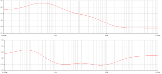
150k || 25pF

47k || 150pF

with my AT420E/OCC MM system ... the rest is self-explanatory!
This is the story of an electrical low-pass filter; whether our pickup is also mechanically capable of reproducing a 20kHz oscillation with the same amplitude as, for example, 1kHz - that is a completely different question.
By the way, we also want to avoid a Q of greater than or equal to 1. The target is 0.5 < Q < 1.
47k || 150pF
with my AT420E/OCC MM system ... the rest is self-explanatory!
This is the story of an electrical low-pass filter; whether our pickup is also mechanically capable of reproducing a 20kHz oscillation with the same amplitude as, for example, 1kHz - that is a completely different question.
By the way, we also want to avoid a Q of greater than or equal to 1. The target is 0.5 < Q < 1.
using input capacitance tuning is worse than using extended Neumann because in the first case the difference in inductances of the right and left channels of the cartridge will lead to a big phase mismatch of the left and right channels. Why this is bad, read here [ https://www.stereophile.com/content/cut-and-thrust-riaa-lp-equalization-page-2 ] . And using for correction first-order LR (or R18C extended Neumann in my circuit) instead of second-order input LCR practically does not lead to interchannel phase mismatch. And I haven’t even said a word about the hysteresis distortions of MM cartridges, which are also maximum at minimum input resistance and maximum input capacitance (remember the currents resonance in a parallel LCR)The Images show that further tuning the 25pF cap to an optimal value and discarding the 7usec Neumann pole leads to better results
So everything really revolves around the concept of group delay distortion.
Dear Nick S.
I would really be delighted if you would write openly and extensively about your findings here in the forum. And not just refer to the Patreon channel, as is so often the case.
To what extent does the capacitive and resistive loading of the pickup on the electrical side influence its distortion behavior?
greetings,
HBt.
- Status
- Not open for further replies.
- Home
- Source & Line
- Analogue Source
- JFE2140/OPA192 jFET/MOS phono preamp with "tube" THD spectrum