Most likely you created these plots by simulation while using a simple Cart model composed of just Lcart and Rcart.with my AT420E/OCC MM system ... the rest is self-explanatory!
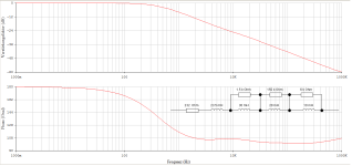
Result with an RC termination is a downgoing -20dB/dec slope at HF.
But a Generator is much more complex than just an L and an R.
And on top of that there is also the cantilevers resonance that in combination with the Generator results in a -40dB/dec downgoing slope
And what you show, -3dB at 100Khz, is technically impossible for several reasons.
Sorry and with all respect, but it is exactly this sort of gross simplification that leads to very wrong conclusions.
Hans
@Hans Polak
I know that - because this is exactly the point of modeling. I'm completely on your side ...
this presentation was a bit mean, sorry. But I already said to Marcel at the end of 2023 that our models are all wrong, or not correct. Let's see what Bob Cordell will contribute to this topic after his long vacation?
😉
HBt.
the higher the input resistance, the lower the current through the ferromagnetic inductance of the cartridge, and the lower the hysteresis distortion (and this, by the way, is the only parameter that is better for MC cartridges than for MM)To what extent does the capacitive and resistive loading of the pickup on the electrical side influence its distortion behavior?

maybe we take a look at:
https://www.pspatialaudio.com/analogy.htm
😎
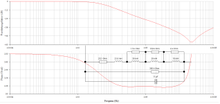
In a joined effort, Bill, Dagfinn and I went into much detail by developing replacement diagrams for MM cartridges, divided into two parts, first the output section with coil, that we called the Generator, and second for the complete Cantilever assembly.
An achievement never realized before to the best of our knowledge.
Having developed the transfer functions for both both parts, we were able to prove that these two parts don't "see" each other, in other words, the external load on the Generator does not influence the Cantilever's movement in any way.
Another benefit by having the...
- Hans Polak
- Replies: 88
- Forum: Analogue Source
https://www.pspatialaudio.com/analogy.htm
I was thinking more of the practical extent and not a basic picture of the electrical load on an induced voltage. No load at all would therefore be the very best, no current flows.the higher the input resistance, the lower the current through the ferromagnetic inductance of the cartridge, and the lower the hysteresis distortion (and this, by the way, is the only parameter that is better for MC cartridges than for MM)
😎
Nick,using input capacitance tuning is worse than using extended Neumann because in the first case the difference in inductances of the right and left channels of the cartridge will lead to a big phase mismatch of the left and right channels. Why this is bad, read here [ https://www.stereophile.com/content/cut-and-thrust-riaa-lp-equalization-page-2 ] . And using for correction first-order LR (or R18C extended Neumann in my circuit) instead of second-order input LCR practically does not lead to interchannel phase mismatch. And I haven’t even said a word about the hysteresis distortions of MM cartridges, which are also maximum at minimum input resistance and maximum input capacitance (remember the currents resonance in a parallel LCR)
I fully understand that you are defending your brainchild.
It was never my intentention to disqualify your concept, I just wanted to find out the properties of this deviating approach.
And in all honesty, I was hoping for more, but it came out as not being the innovative Jack of all trades as propagated, at least not IMO.
Group delay errors of a few micro seconds around 20Khz, while our auditory system can hardly notice a few msec around 3Khz and no phase errors at all above 5Khz cannot be called “big phase errors” so this argument doesn’t hold.
But in the end almost all changes to the FR with 150K//25pF are in the ultrasonic area, so chances are that we won’t notice any difference.
And that is exactly the only point that matters, not the specs and not the plots but whether the perceived sound impression improves with the 150k//25pF onboard solution.
I won’t further contribute to this thread and wish you success with your phono preamp.
Hans
Yes, and this is exactly what is needed, = neither the frequency nor the phase characteristics depend on the inductance-capacitance-resistance of the input circuit.But in the end almost all changes to the FR with 150K//25pF are in the ultrasonic area
for those who trust only their earsthe only point that matters, not the specs and not the plots but whether the perceived sound impression
someone sees even more https://www.patreon.com/posts/93731535We see a mechanical and an electrical part ..!
https://c10.patreonusercontent.com/...=bn3T43u2lOBQAuXQNmq6XMuE8viviOVNh8n1JqWjSb8=
Nick,someone sees even more https://www.patreon.com/posts/93731535
that doesn't help anyone here - we don't want a Patreon paywall or a login. We want to communicate with each other as directly as the forum allows.
simply click a link - paywall or login are unnecessarywe don't want a Patreon paywall or a login.
ok,simply click a link - paywall or login are unnecessary
thx.
👍
Hans model of the mechanically moving part shows that there must be an upper mechanical limit reflected on the electrical side. f_limit < 25kHz.
Well, that's a truism and the pickup manufacturers usually specify this limit as well. In my above example of the AT420E, AT says 25kHz is the upper limit. And exactly in this range the termination with 47kOhm || 150pF is exactly correct, i.e. if you look at the (let's say incorrectly "Bode") Bode diagram between 10kHz and 30kHz, everything is totally correct quantitatively. Multiplication with the mechanical transfer function is now welcome.
Posting #43 illustrates exactly what it is supposed to illustrate.
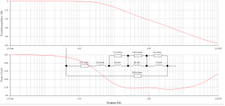
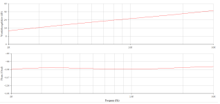
Absolutely correct,And what you show, -3dB at 100Khz, is technically impossible for several reasons.
but even without the cantilever component I do not show a cut-off frequency at 100kHz.
34.75kHz (47kOhm)
vs.
77.1kHz (150kOhm)
So we are above the mechanically specified limit ... that's good. Of course, you won't suddenly get more AUDIO out of the back. And that's why it doesn't really matter whether Nick adds a zero at the end.
However, if it reduces the group delay distortion or even improves the stereo width, then go for it.
I get more audio up to 48 kHz with very low budget MM cartridge Audio Technica AT91you won't suddenly get more AUDIO out of the back. And that's why it doesn't really matter whether Nick adds a zero at the end.
@Hans Polak
To identify the path ("die Strecke"), you must have recorded the output voltage of the tactile sensor (DUT). The specially made test record with pink noise was used for stimulation... right?
And what exactly did your measuring amplifier look like? For example, I ask about its complex input impedance. Was there an electrical load on the sensor?
You know what I'm getting at!
kindly,
HBt.
Psst
Would it have been possible to cut a linear sweep from 100Hz to 100kHz onto the test record?
In the meantime, some questions have been answered via PM.
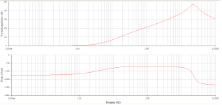
A linear sinusoidal sweep from 2kHz to 30kHz was used as the excitation signal for system identification: TEST-LP 33+1/3 rpm. This automatically means that the published impedance model is only valid within these limits; it shows an increase of a constant +17dB/decade. No more and no less.
The Rp & Cp-termination confirms nothing more than the Audio Technica manufacturer's recommendation.
There was no real measuring amplifier during data recording.
kindly,
HBt.
Attachments
- Status
- Not open for further replies.
- Home
- Source & Line
- Analogue Source
- JFE2140/OPA192 jFET/MOS phono preamp with "tube" THD spectrum