Hi Rob,
No, that heat sink isn't for the Leach. I think it is too small.
However, I am quite surprised that it seems to dissipate better than how it looks. It is only warm when one channel of Mini-Aleph is running, but then it is only 35W.
The Leach will get the Conrad's that are still in virgin form 🙂 I want to test my drilling and taping accuracy with other el cheapo heat sink first. Oh yeah, you did see many holes on that heat sink, LOL.
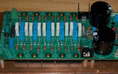
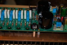
I didn't have anything to measure, the clip that I used in the picture seem to "hug" the transistor tighter with the al-oxide which is likely due to the extra thickness. Maybe it is just me, another perceived advantage of the clip is that it kind of works like a wide washer. You can see from my pictures that the pressure point was right on the top of the mid-point of the transistor.
Frankly, given my normal listening level, the Leach probably will only need to crank out less than 5 wpc most of the time. A little less heat transfer efficiency probably won't hurt the transistors. That's why I chose the clips because it is easy for me with my lack of metal work skills ......
No, that heat sink isn't for the Leach. I think it is too small.
However, I am quite surprised that it seems to dissipate better than how it looks. It is only warm when one channel of Mini-Aleph is running, but then it is only 35W.
The Leach will get the Conrad's that are still in virgin form 🙂 I want to test my drilling and taping accuracy with other el cheapo heat sink first. Oh yeah, you did see many holes on that heat sink, LOL.
I didn't have anything to measure, the clip that I used in the picture seem to "hug" the transistor tighter with the al-oxide which is likely due to the extra thickness. Maybe it is just me, another perceived advantage of the clip is that it kind of works like a wide washer. You can see from my pictures that the pressure point was right on the top of the mid-point of the transistor.
Frankly, given my normal listening level, the Leach probably will only need to crank out less than 5 wpc most of the time. A little less heat transfer efficiency probably won't hurt the transistors. That's why I chose the clips because it is easy for me with my lack of metal work skills ......
The clip does have the advantage that it hits the transistor in the middle. You should use a washer under a through screw, anyway, to even out the pressure on the transistor. The clip has the further advantage that the screw hole is not under the transistor, where the screw can lift the surface of the sink if torqued too much. I see this as its biggest advantage. Screwing up the area around the hole could cause a real big problem. Might have to re-machine it flat.
I think the best situation would be to place a rigid bar bridging a row of output transistors, and screwing the bar to the heat sink between the transistors. Unfortunately, the board doesn't provide any room between the transistors for such screws, and screwing the bar down at each end of the row is probably insufficient to keep it from bending. A bar's hold-down screws could be passed through the transistors' holes with the same issue as before. However, the bar could then provide as good or better effect than individual washers on each transistor regarding even pressure, and provide some fashion of heat sinking on the top sides of the transistors.
I think the best situation would be to place a rigid bar bridging a row of output transistors, and screwing the bar to the heat sink between the transistors. Unfortunately, the board doesn't provide any room between the transistors for such screws, and screwing the bar down at each end of the row is probably insufficient to keep it from bending. A bar's hold-down screws could be passed through the transistors' holes with the same issue as before. However, the bar could then provide as good or better effect than individual washers on each transistor regarding even pressure, and provide some fashion of heat sinking on the top sides of the transistors.
Re: sping clips
Yes Rob, it is good enough for all I can tell. But it is not as good as having a rigid bar bridging a row of output transistors, and screwing the bar to the heatsink.
(Please note that the photos provided are of the clips I bought, but the implementations are not mine.)
I have been using this approach with chip-based amps like the PBA-200 where I have (4) LM3886 on the same heat sink. It works great!
rob3262 said:...
Duda, you're satisfied with the amount of force the clip imparts?
...
Yes Rob, it is good enough for all I can tell. But it is not as good as having a rigid bar bridging a row of output transistors, and screwing the bar to the heatsink.
(Please note that the photos provided are of the clips I bought, but the implementations are not mine.)
pooge said:...
I think the best situation would be to place a rigid bar bridging a row of output transistors, and screwing the bar to the heat sink between the transistors.
...
I have been using this approach with chip-based amps like the PBA-200 where I have (4) LM3886 on the same heat sink. It works great!
what insulators http://delta-audio.com/Leach_pics.htm uses
how they compare to aluminum oxyde ceramic pads 4180g
does the driver transistor use any heatsink
how they compare to aluminum oxyde ceramic pads 4180g
does the driver transistor use any heatsink
does the driver transistor use any heatsink<?>
Like many of our newbie questions, this was touched upon earlier in the thread:
http://www.diyaudio.com/forums/showthread.php?postid=1727339#post1727339
I'm using an aluminum standoff and a small heat sink, just to be sure. I assume we want to ensure electrical isolation of the driver mounting tab from the main heatsink, so I will use a plastic washer in addition to a mica insulator.
Any recommendations here?
-Chas
Attachments
Chas,
At the rail voltages that you mentioned, those driver heat sinks look adequate. I've had a set like that with 1/2" fins at 60V for 6+ years of near daily use without failure. I see no need for the metal standoff to the main sink. Watch that the screw head on the mount next to it doesn't short the heat sink to ground if you aren't isolating the driver
Bob
Hi,
or change the To220 drivers to To126 devices and the heatsink then sits on top of the device and you have no problem with shorting to the tracks underneath the device. The sink can now be direct mounted to the To126 without needing an insulator, thus keeping the device cooler.
I find that the To126 with 20C/W sinks do not get warm on +-58Vdc. Just slightly warmer than cold.
Comp diode PCB placement
can anyone think of a reason to not relocate the compensation diode PCB using, say, 6" long twisted leads - placing compensation in the middle of all the output transistors?
Today is drill day...
can anyone think of a reason to not relocate the compensation diode PCB using, say, 6" long twisted leads - placing compensation in the middle of all the output transistors?
Today is drill day...
That's what I would do. However, I would put both the resistors R25 and R26 of Leach's circuit in, as shown in
Leach amp
Leach says he uses these to isolate stray capacitance from the leads in his FAQ.
Jens combined these resistors into one. Just cut the value Jens specified and add an in-line one of appropriate value between the board and the leads to the diodes.
Leach amp
Leach says he uses these to isolate stray capacitance from the leads in his FAQ.
Jens combined these resistors into one. Just cut the value Jens specified and add an in-line one of appropriate value between the board and the leads to the diodes.
Watch that the screw head on the mount next to it doesn't short the heat sink to ground if you aren't isolating the driver
OK Bob.
I'm using a mica(w/thermal compound) under the (T21/22)driver, with a nylon washer on top- adequate?
Today is drill day...
Way to go, Rob! Are you using a drillpress(I hope so)?
I took my heatsinks over to Brutepuppy's place to punch/drill/tap.
His technique of clamping the work to the drill base and then drilling and tapping in sequence (using the chuck for precise vertical alignment of the tap) one hole at a time, allowed me to do both heat sinks (over forty 4-40 tapped holes) without breaking a single drill or tap!
(Thanks again BP)! 🙂
-Chas
Attachments
Rob
If you go back and read Dr. Leach's details on the TIM amplifier I believe he has some comments concerning the distance the compensation diodes should be from the Vbe. Something to do with stray capacitance that is why he chose this layout scheme. Jens has done a superb job in keeping with this theme by placing the string under the main board.
Tad
clm811 said:... allowed me to do both heat sinks (over forty 4-40 tapped holes) without breaking a single drill or tap!
(Thanks again BP)! 🙂
-Chas
Oh quit bragging! 😉
Pooge / Tad,
Thanks. I had originally read Leach's writeup as potential oscillation when mounting vbe transistor to the sink.
I've already loaded the PCB's with parts, not likely to pull a resistor if not necessary.
Somehow I found myself working from the wrong schematic, v9.05.10, which depicts R70 opposite TH1/R29. Silly me, there is no R70 on the board
so...
Download v5.6.10, delete the other rev. Throw out moving the (under)compensation SMD pcb. I was going with 3 diodes, but will now load the 4th and locate the PCB back to the intended location
took my heatsinks over to Brutepuppy's place
Nice work guys. Chas, have you guys made voltage measurements of the front ends, if so, results? My zener debacle is a setback. Despite AndrewT's solid advice on corrections, I am replacing all zeners before moving forward
Way to go, Rob! Are you using a drillpress(I hope so)?
Actually, I found this drill in Grandpa's tool chest. A #50 drill bit yields a #43 hole... I can crank out a 6mm deep hole in just under 40 minutes. I should have all my heatsinks drilled by August...
An externally hosted image should be here but it was not working when we last tested it.
Actually, I found this drill in Grandpa's tool chest. A #50 drill bit yields a #43 hole... I can crank out a 6mm deep hole in just under 40 minutes. I should have all my heatsinks drilled by August...

Rob,
Good joke!
Really- Do you have access to a drill press? I'd originally planned to drill and tap by hand (thanks to BP I was spared the grief)!
IMHO, anyone who can gain access to a drill-press should do so (unless you're a masochist).

It's easier and safer using a tapping guide or "center" (which sells for <$20 on ebay) or, better still, a "tapping head".
See the following link, which even has an instructional video:
http://www.jjjtrain.com/vms/cutting_tools_tap/cutting_tools_tap_10.html
Best wishes!
-Chas
p.s. no smoke test yet(I've got the kids home during their short break from school) 🙂
I accessed a drill press and auto center punch where I work for drilling, tapped by hand at home
I took argofanatic's advise on the spiral flute tap, which performed as expected. I chose a bottoming version as my Conrad sinks have an 8mm base, all holes are blind to 6.5mm. Chips readily pulled up and out of the holes
Used compressed air to clean the tap between holes, blow out any remaining debris. Tap Magic lube was recommended, several formulations available. The stuff did it's job fine, but I have no compairison to the other lubes recommended here @ DIY
no issues with the first 19 holes, five heatsinks to go. The chosen 5/8" aluminum standoffs leave the PCB too high for mounting MJL15032/15033 to the main heatsink. Another noobie annoyance to deal with
Final step will be to debur the holes, then run the face of the sink over 1200+ wet/dry paper to smooth.


To All,
You should try the hand drill with a small bit before making these statements. The excessive down force and very slow rotational speed will yield a very defined chip. The time it takes to drill just one small #4 hole can be less than one minute. You also have the advantage of being able to feel what is going on at the bit tip which heads off disasters. Do NOT use this on your project!!!
The majority of home do it your selfers do not realize that the common modern drill rotates far faster than is needed. This excessive speed yields higher horsepower ratings which make production cheaper. You have to give the bit time to pull up the metal before broaching it off. Less heat, less problems. The only real dilemna is keeping the brace and bit vertical.
The bit pictured above which is a variable diameter wood bore will make a nice clean hole in wood FAST. I use one quite often to drill holes for electrical outlets in my house.
Tap magic is fabulous stuff , well recommended if you can find it. It is made with cinnamon oil and other organic lubricants.
I also mounted my pcb's high off the sink. I chose to use separate heatsinks attached to each driver in the vertical position. I stabilized them to the big caps with hot melt glue. Isolated of course. They run very cool to the touch.
Is anyone building with separate regulated frontend power supplies. Would like to hear about it.
Tad
still not after two years.tryonziess said:[BIs anyone building with separate regulated frontend power supplies. Would like to hear about it.[/B]
The original regs did not work as expected and the Cetoole is on hold at the moment.
- Home
- Group Buys
- Jens Rasmussen Leach clone group buy