Tad, the bridged Leach was fine, although I only used them for sub duty below 60 Hz. They were fed with an eq that added 6 dB boost at 24 Hz with a high Q high pass filter. It didn't have quite the same oomph as my bridged DH-500, despite having twice the PSU caps.
Rob, I used 3 x 15,000 uf snap ins per rail per channel. Nothing special, United Chemi-con from Apex Jr. I haven't tried high end caps, so I won't comment.
As for how much to use, I've heard a variety of rules of thumb. I've run my Leach amps as low as 10,000 uf per rail. I am not sure that there is much improvement at 45,000 per rail, but I am not using them full range.
As much capacitor as you can fit in the case is a pretty good rule on the maximum end. The caveat with that is the inrush current will challenge your rectifiers and line fuse. The bigger your cap bank and transformer the better your inrush limiter needs to be. My line voltage drops 10-12 volts with a CL30. A relay//resistor soft start is in my future.
tryonziess said:Fel-Sic caps made in France
Felsic is a range, Sic-Safco is the brand.
Felsic covers a dozen screw terminal capacitor types, three temperature classes, and several uses.
The LP type is the exotic of the Felsic bunch, similar hand grenade look as the Mundorf M-lytic-hc and also intended for bottom surface cooling with a dedicated mounting bracket.
(Sic-Safco was the preferred lytic brand of Hiraga and his l'Audiophile cell mates. The M. de l'Audiophile store in Paris was one of the rare places where to buy Felsic lytics easily. Hail to the world wide web.)
Jacco,
Who else are you including in Hiraga gang of Audiophiles. I had been under the impression he was a lone ranger type. He has many followers but comrades?
Thanks for the Sic-Safeco cleanup. Audiophile grade, no wonder they sound so good. They are not cheap.
Tad
Who else are you including in Hiraga gang of Audiophiles. I had been under the impression he was a lone ranger type. He has many followers but comrades?
Thanks for the Sic-Safeco cleanup. Audiophile grade, no wonder they sound so good. They are not cheap.
Tad
tryonziess said:Who else. They are not cheap.
Depends, twelve fifty for a 7 year old 47K isn't that bad : here
JCP Vereker, for example, see my jibberish on the Naim 552 thread.
A commercial amp designer overhere used them when i first met him +20Y ago, still does in his $24K top model power amp.
Plus the usual pack of froggies, like Jadis et al.

any drawback to specifying a 450V cap on a 70v rail?
(edit) upon closer inspection, the site I was looking at was filled with typo's
-anyhow-
maybe someone (Bob?) can suggest some methods of implimenting a capacitor bank, daisy chaining all those leads together and getting the current to the amp board
(edit) upon closer inspection, the site I was looking at was filled with typo's
-anyhow-
maybe someone (Bob?) can suggest some methods of implimenting a capacitor bank, daisy chaining all those leads together and getting the current to the amp board
rob3262 said:any drawback to specifying a 450V cap on a 70v rail?
Other than being lower capacitance in a similar package and probably more costly?
maybe someone (Bob?) can suggest some methods of implimenting a capacitor bank, daisy chaining all those leads together and getting the current to the amp board
If using screw terminal caps, just make a heavy copper bus for the ground side and daisy chain the rails using crimp fittings.
For snap in caps, I've made pcbs just routing the copper into three large strips. They were tough to solder - 2x6" 2 oz double sided copper can soak up a lot of heat. I ended up using a propane torch to heat the board after failing to get a good joint with a 100W gun.
An alternative is to mount the caps in clamps like you would for screw terminal caps and make a heavy bus out of tinned 12 ga. or larger wire soldered to the terminals. You'll still need 100W or so, but it's a lot easier to solder to than a large area of copper.
For this build, I bought a bunch of Aleph PSU boards from chipamp.com. It'll end up being 45,000 uf per rail per channel again, plus 10,000 on the board.
I bought some 450 volt Rifa caps and they blew out the rectifiers everytime I hooked them up. They test good. Any ideas.
Tad
Tad
Were they NOS? Maybe they need reforming - put a 10-20K 2-3W resistor in series and charge them up to at least your planned working voltage. When the charging current drops to a few volts over the resistor use the resistor to bleed them down. They should now be good to go.
Otherwise, test good how?
Otherwise, test good how?
Does anyone
have a parts list for the leach? I bought these boards long ago but never got parts.
have a parts list for the leach? I bought these boards long ago but never got parts.
???
Bob, the digikey numbers are missing for most of those!
Haha, thanks. That will be helpful, if anyone updates the list please post. I'll post if I get to it first.
Bob, the digikey numbers are missing for most of those!
Haha, thanks. That will be helpful, if anyone updates the list please post. I'll post if I get to it first.
Too late
Hey guys,
I'm new to this forum and this is my first post. I'm currently looking out for an amplifier project, and from what I've read here this PCB-Version of the famous LEACH AMP seems to be quite promising (thanks to Jens unbelievable effort).
As you might guess, I could byte my bum for geeting into this topic after the succesfull group buy 🙁
Therefore my question is: Is anyone perhaps willing to sell me two frontends and two standard Leach PCB?
Please contact my by PM. I tried to mail Tad, but I've got too few posts for directly mailing people.
Sincerely
Georg
Shorso,
This group buy was for a single piece pcb with 5 output PAIRS.
I currently do not have any boards left.
If we can ever get the super Leach pcb validated there will for sure be a group buy for those boards. That particular design does have separate frontend and output sections.
Welcome to the forum. Stay tuned in and eventually something will come up. There is an abundance of knowledge here and many great projects to take up ALL of your spare time.
Check out the wiki section and you might find something there which you can build meantime.
Tad
Hi Tad,
thanks for the quick reply!
I got a little confused while reading in this not-so-short thread, because somehow the group buy topic smeared out in a builders thread...
Thank god I'm on holiday right now, otherwise it would be hard staying away from this forum 😀 It's really amazing how many people share their knowledge here. Even in our institute it's hard to convince people of the benefits of the open source culture.
I'm sure someone already had this idea, but wouldn't the new ThermalTraks fit in this schematic quite well?
Anyway, if someone has boards from this group buy spare and is willing to sell'em, please drop me a note!
Cheers
Georg
Schorso, I have sent you an email.
I am also under the impression that this would be a good application for the thermal trak transistors. What I believe is the problem can be found on two other active threads at this time. It seems that a majority consensus can not be reached as to just how many diode groups would be needed.
Roender has successfully designed and built a sweet little amp using the thermal traks. He does not use all of the diodes in the Vbe multiplier. My thinking is that the diode in the transistor should work like a stand alone device so just use 4 like the Leach design. Not having enough knowledge myself I leave these things to others to contemplate.
Anyway with very few new toys being designed here as of lately maybe a good Thermal Trak Leach clone will come along. Also, for most budgets this device is not CHEAP. Buying 40 or 50 thermal traks and matching could put a hobby budget off track. Jens would be my choice for this design however he is quite busy these days.
Anyone have any news about the Super Leach layout?
Tad
The Leach can use three or four diodes in the upper leg of the Vbe multiplier.
This suits a two pair output stage, but don't use that with 4ohm speakers.
I would be very tempted to use four diodes and bypass one of them with a pot to trim the effect that diode has on the tempco.
This suits a two pair output stage, but don't use that with 4ohm speakers.
I would be very tempted to use four diodes and bypass one of them with a pot to trim the effect that diode has on the tempco.
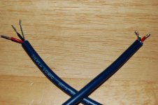
Input wiring
Doing the final signal wiring, and have a question:
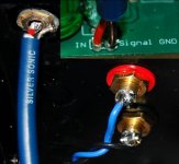
The input cable I've chosen is a shielded, symmetrical twin-conductor (red for positive, black for negative plus a shield with drain wire).
Since the input GND on the PCB is already wired to the star GND,
should the drain wire(shield) be connected to the black wire at:
a) the RCA jack(which is insulated from the chassis),
b) the point of connection to the audio GND on the PCB , or
c) both?
Thanks in advance.
-Chas
Doing the final signal wiring, and have a question:
The input cable I've chosen is a shielded, symmetrical twin-conductor (red for positive, black for negative plus a shield with drain wire).
Since the input GND on the PCB is already wired to the star GND,
should the drain wire(shield) be connected to the black wire at:
a) the RCA jack(which is insulated from the chassis),
b) the point of connection to the audio GND on the PCB , or
c) both?
Thanks in advance.
-Chas
Attachments
Re: Input wiring
According to Morgan Jones, (a) - always connect the shield to the ground of "source" end. In this case, the RCA end.
clm811 said:Doing the final signal wiring, and have a question:
The input cable I've chosen is a shielded, symmetrical twin-conductor (red for positive, black for negative plus a shield with drain wire).
Since the input GND on the PCB is already wired to the star GND,
should the drain wire(shield) be connected to the black wire at:
a) the RCA jack(which is insulated from the chassis),
b) the point of connection to the audio GND on the PCB , or
c) both?
Thanks in advance.
-Chas
According to Morgan Jones, (a) - always connect the shield to the ground of "source" end. In this case, the RCA end.
- Home
- Group Buys
- Jens Rasmussen Leach clone group buy