Hi Tad,
The press at work is speed adjustable, with a guide listing different materials. Aluminum was one of the slowest drill speeds, right above plastic. I drove the bit in slowly, letting the tool do the work.
re - regulated front end, I picked up several PSU2.2's from Bob Ellis. Antek 1000VA 50-0-50, then a 50VA 6V in series to the supply set at 70.0v I will be using one regulator per stereo pair.
Eventually...
Slow & steady may not win the race, but if it keeps me from smoking $5 transistors....
Andrew,
How much current should I have available for the regulated frontend on the 10 output device Leach. I believe Bob had mentioned that 500ma would be more than adequate to power this amp. Tad
How much current should I have available for the regulated frontend on the 10 output device Leach. I believe Bob had mentioned that 500ma would be more than adequate to power this amp. Tad
The front end does not include the drivers.
The current requirement is tiny for the front end.
Go and calculate all the quiescent currents and then look at which ones can vary with signal and by how much.
Allow a bit for capacitor charging at worst case HF and add them all up.
If the variation with signal is low consider using a CCS + Shunt reg.
1000VA is enough for 500W to 1000W of total output power.
50-0,50-0 should provide at least 200W into 8r0. That's just 400W total for two channels. You might get 250W+250W into 8r0 if the PSU is built for power.
400W+400W into 4r0 will stretch the transformer if used for PA/disco, for normal music it will be just fine.
50-0,50-0 should provide at least 200W into 8r0. That's just 400W total for two channels. You might get 250W+250W into 8r0 if the PSU is built for power.
400W+400W into 4r0 will stretch the transformer if used for PA/disco, for normal music it will be just fine.
Ground connections
OK, Guys. I'm almost ready to hook everything up; BUT, knowing that we have here a vast resource of information, I did a search for info on "ground connections". To my surprise, I found as many different recommendations as there were contributors! So many, in fact, that I'm feeling a bit confused and discouraged (and I'll bet I'm not alone)...
While I do not wish to start an argument or a flame war , I'll stick my neck out and ask for guidance in this thread, specific to this Leach Class A/B amp, regarding connection of the various "grounds" without excessive theory or unnecessary complication(there are already enough threads suffering from that). Basically, what connects where for minimum hum and noise?
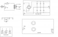
Attached is a diagram showing a center-tapped transformer, diode bridge with smoothing caps(PCB-mounted in my example), one token ground-decoupling circuit, and the (Rasmussen-Leach) amp PCB. For simplicity, lets say the amplifier is built upon a conductive metal chassis. All possible ground connections are given letters, and a legend of conventional ground symbols is provided for reference, taken from Wikipedia:
http://en.wikipedia.org/wiki/Ground_(electricity)
Naturally, if there are any errors please feel free to point them out.
Please/thanks in advance!
-Chas
OK, Guys. I'm almost ready to hook everything up; BUT, knowing that we have here a vast resource of information, I did a search for info on "ground connections". To my surprise, I found as many different recommendations as there were contributors! So many, in fact, that I'm feeling a bit confused and discouraged (and I'll bet I'm not alone)...
While I do not wish to start an argument or a flame war
, I'll stick my neck out and ask for guidance in this thread, specific to this Leach Class A/B amp, regarding connection of the various "grounds" without excessive theory or unnecessary complication(there are already enough threads suffering from that). Basically, what connects where for minimum hum and noise?Attached is a diagram showing a center-tapped transformer, diode bridge with smoothing caps(PCB-mounted in my example), one token ground-decoupling circuit, and the (Rasmussen-Leach) amp PCB. For simplicity, lets say the amplifier is built upon a conductive metal chassis. All possible ground connections are given letters, and a legend of conventional ground symbols is provided for reference, taken from Wikipedia:
http://en.wikipedia.org/wiki/Ground_(electricity)
Naturally, if there are any errors please feel free to point them out.
Please/thanks in advance!
-Chas
Attachments
Chas,
Some of the best ground schemes can be found in the Pass section. The way Nelson connects most of his grounds is to use a common star for all of the board circuit grounds leading back to the ground for the power supply caps and transformer center tap. Then semi-isolate the chassis ie, power cord,
ground to this with a thermistor.
Make sure the power cord ground is firmly fastened to the chassis DIRECTLY. Make sure to include the speaker grounds in this common location.
The pcb screw mounts have to be isolated from the heatsink on Jens board ie, nylon standoffs or the like.
I really do not think you will have much problem with noise in this design. My amp is dead quiet. I also use a full isolated ground on my projects. It is a 10 foot copper rod driven into the ground and connected to the ground on my dedicated power plug at the wall. This is completely isolated from the rest of the house. Works good. Of course the rest of my house only has 2 prong plugs.
Now get some Miles Davis and see what the Leach can do. Tad
Chas -
As Tad said, it is an absolute requirement to connect the ground lead on the power cord, A in your picture directly to the chassis. Use a star washer or lug to ensure that it establishes a good contact with the chassis.
For an extra bit of clarity early Saturday morning:
Let's use point D in your picture as the star ground.
The signal ground is one is separated from the power ground by R4. Connect the input jack ground to E and also run a wire from E to D. (28 gauge or similar) In Leach's article he mentions that if you experience ground loops, you can eliminate the D-E connection.
The speaker output F is also the board's power ground. I should connect to the star, D. Same with the transformer center tap B. Use heavy gauge wire (14 gauge or heavier) for this connection and the ones below.
Connect the speaker output ground F to D.
I'd consider C just the other end of the bus between the power supply caps. For belt and suspenders grounding, you can connect it to D. If using screw terminal caps, each one gets a wire to D, and C doesn't exist.
So far we have the amp electrically isolated from the chassis. It will work this way. This is the only way I can get mine quiet if connected to my laptop and it's noisy PSU.
Most grounding schemes connect the star ground to the chassis. Connect G to D and H/I to the chassis and you're set. This can be at or near the point you have connected the power cord ground or another convenient spot assuming good electrical connection between chassis panels. Be sure that the diodes are fairly high current rated (3+A continuous) and use a 5W resistor. You can substitute a thermistor for the resistor//diodes as Tad pointed out.
Pass speaks of grounding in many of the threads in his section of the forum. I'd give his (and the other big names) thoughts on the subject much more weight than regular members like me. As I see it the common thread is star grounds for the amp isolated from earth by diodes//resistor or thermistor. Leach adds the resistive connection between power and signal grounds, which seems to anticipate ground loop problems.
Another item gleaned from building a Hafler kit years ago concerns wire routing. The DH500 power leads are twisted tightly together and run against the chassis as long as possible. Hafler said that this contributes to noise prevention and not doing so could result in hum. True or not, it makes your build look more professional. 😉
HTH
Chas,
I forgot, like Bob mentioned, that Dr. Leach goes into this area of grounding on his TIM site. If you look around meticulously there are some side links on the site which will take you to some of the actual building notes from the magazine article which is pretty specific. There are also some hints in the super leach notes.
Good luck Tad
Bob,
There are some really neat and cheap isolation transformers which are built into the speaker leads for use with computers. They come 47k impedance and work flawlessly. I could not listen to web generated music without them. The Delta audio driver board also made a world of difference. When did you build a Hafler? How many of these projects have you put together?
Tad
The pcb screw mounts have to be isolated from the heatsink on Jens board ie, nylon standoffs or the like.
Wow, I'm glad the ground question came up as I was unaware of this requirement.
 and I just purchased replacement aluminum standoff's to lower the PCB...
Rob - nylon washer and screw will do the job with your new standoffs.
Tad - I build the Hafler in 1984 (showing my age). It wasn't much of a kit - just hook up the power supply, connect it to the amp module and you're done. IIRC, it took less than two hours.
I've build a good number of amps including hollow state, but only a few ended up in respectable enclosures. I'm glad Coulomb has a GB going for enclosures and heat sinks...
mjl4281 3A @60Vce
2sa1553 2A @60Vce
2sa1943 1.5A @60Vce
Choose you output devices with care, both to suit your load and PSU.
2sa1553 2A @60Vce
2sa1943 1.5A @60Vce
Choose you output devices with care, both to suit your load and PSU.
Fuse selection
OK. Time to select the appropriate fuses. I looked at Jens' BOM and I didn't see a listing of the fuses.
I re-read Leach's BOM and he specifies 8A Slow-Blow type for the line (AC) fuse, and 5A Fast-Blow for the rails(DC). His selection is based upon a 2-channel (2 pairs output devices) amplifier with 58vdc rails.
In my case, I'm building a mono amplifier with 56vdc rails and 5 pairs of output transistors; incidentally, the on-board caps (C21,27) are 3,300uf. The original stereo amp from which I got my transformer(110Wpc/8ohms) had a 6.3A line fuse and 5A rail fuses (since it wasn't specified, I'll assume all five fuses were of the fast-blow variety).
I did a search here and saw one of Andrew's posts:
Would 6.3A AC line and 4A rail fuses(F1,F2) be a good choice?
Also, I believe I'd read somewere to avoid slow-blow fuses in solid-state power amps, but I can't locate the link.
I'd appreciate any thoughts or suggestions on fuse selection.
-Chas
OK. Time to select the appropriate fuses. I looked at Jens' BOM and I didn't see a listing of the fuses.
I re-read Leach's BOM and he specifies 8A Slow-Blow type for the line (AC) fuse, and 5A Fast-Blow for the rails(DC). His selection is based upon a 2-channel (2 pairs output devices) amplifier with 58vdc rails.
In my case, I'm building a mono amplifier with 56vdc rails and 5 pairs of output transistors; incidentally, the on-board caps (C21,27) are 3,300uf. The original stereo amp from which I got my transformer(110Wpc/8ohms) had a 6.3A line fuse and 5A rail fuses (since it wasn't specified, I'll assume all five fuses were of the fast-blow variety).
I did a search here and saw one of Andrew's posts:
The rails run at +-58.55Vdc from a 1kVA 40Vac transformer...The test was carried out at 241Vac with the rails @ +-58.9Vdc...The 311W result pulls the supply voltage at the PCB fuses down to +-57.65Vdc. The F3.1A rail fuses survived the test.
Would 6.3A AC line and 4A rail fuses(F1,F2) be a good choice?
Also, I believe I'd read somewere to avoid slow-blow fuses in solid-state power amps, but I can't locate the link.
I'd appreciate any thoughts or suggestions on fuse selection.
-Chas
Chas,
The correct way to do this is run the math. I did not go that route. I use an inline circuit breaker for the incoming power mounted to the rear of the chassis. It is what all of my Mcintosh amps had so I went that way.
For each rail fuse block I use 4 amp fuses with 70 volt rails. 4 times 70 is 280 watts. They have not blown out yet. Using a smaller fuse will protect things better -- my opinion anyway.
On the rails I think you could get away with fast blow types. You will not have that good of luck before the power supply with a fast blow. Try using slow blow for the incoming AC power or install a circuit breaker. They are cheaper to reset than replacing fuses all the time. Those fuses are expensive at Radio Shack.
One little caution: Use an insulated screwdriver when adjusting the bias pots. Speaking from dumbville here. Had a big blowout with my metal shaft. I use Dr. Leach's method of adjusting by reading from the fuse holder. Andrew and most others read at the emitter resistors. I found Leach's approach easier. You read total rail bias by measuring amps with the DMM attached across the fuse blade without a fuse in. I could not easily get to the emitters with everything in the chassis.
Tad
I used the trial and error method - I ended up with a 6A slow blow in the mains line feeding a 1KVA transformer and 90mF cap bank. That was as small as I could go without blowing regularly. It took 10A fast blow.
I use 3A per rail on my Leach amps downstream of the cap bank where there isn't an inrush issue. It's more than enough to handle home use - I haven't blown one in over 6 years even when bridged driving my subs (except for a slipped test lead)
I use 3A per rail on my Leach amps downstream of the cap bank where there isn't an inrush issue. It's more than enough to handle home use - I haven't blown one in over 6 years even when bridged driving my subs (except for a slipped test lead)
So we read that Bob has a 90mF cap bank. Tad was previously looking for maybe a group buy on some big caps.
Tad, you still in the market for big fatty capacitors?
I hit up Apex Jr for some 22kuF caps, found that they're China knockoffs and I have concerns that my power supply performance will suffer. So I find myself in the market for new electrolytics but man, the big ones really are expensive. I have some NAD amps that utilize the capacitor bank approach.
Is there any rule of thumb for running a cap bank. Like, more is better, whatever fits in the chassis, etc.
The big caps have screw terminals and I think a robust physical connection can be made that would give electrical performance. Smaller caps are likely to be snap-in leads. Would these snap-in style just get mounted to perf board and solder a big fat wire along the run?
- Rob
Bob,
How did that bridged Leach thing turn out. Been really thinking about building to stereo units and bridging each independent channel. Did you have any overheat problems or distortion artifacts. Should be able to get 800+ watts from 65 volt rails. It is like horsepower. Who needs it just fun to own. Nice to brag about too.
Tad
Rob,
I am always in the game for some good high grade power supply caps. If we could buy maybe 400 Rifa caps we could get a decent discount. 22000, 33000, 47000 uf -- 100 volt Rifa caps would handle most projects. I prefer this brand. They have a good reputation and are long lasting.
Someone wish to explore the cost of these in volume and I will take about 40 of them.
The 37000 uf caps I got from JEA capacitors on ebay are really good and have current date codes.I was surprised being ebay and all. I have 4 in the Leach and 8 in the A-75.
One note-- I bought some Fel-Sic caps made in France and was able to distinquish better sound from them immediately. It is a quality item. They were rated 63 volts so I took them out before I had a catastrophe of sorts. A GB on them would suffice. Large valule 100 volt caps are just plane expensive!!!
All interested in this please respond. Tad
- Home
- Group Buys
- Jens Rasmussen Leach clone group buy