tryonziess said:Tony made a remark a few posts back concerning the ability to use this new cascode front end without using a cascode output stage. I do not know much about this so what would have to be implemented to use a parallel output -- ie, 10 transistor -- without cascode.
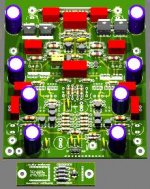
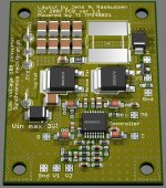
Jens what program do you use to create those realistic board layouts. Tad
The layout is done in Eagle (www.cadsoftusa.com) and i export to povray that does the rendering.... see this page: http://www.matwei.de/doku.php?id=en:eagle3d:eagle3d
rolandong said:Hi Jens,
Would it be possible to provide an option to use 5mm film caps by providing extra pad in the middle (C47, C39, C33, C41, C43, C26, C43, C2, C15), so that other film caps can be used ex.Vishay Roederstein MKP1837, Epcos, etc.
regards,
Roland
I'll see what I can do.... maybe the silkscreen will be scrapped for these parts.... will this be ok?
\\\Jens
Attachments
Jens, Since you added the updated feedback and other modifications to the original 10 transistor layout it seems we have kind of steered off course here. I assume that the ideas you hoped to implement to the original board were improvements.
Do you still want to make a prototype board as you originally proposed and see how the new modifications might sound. I am still interested in this endeavor.
I also would like to see the super leach cascode frontend implemented in either a cascode output arangement or standard multiple parallel output.
I would be willing to proceed with the modified original design while we work out the details for the cascode amp.
Have you got gerber files made with the modifications ready to be prototyped. There is enough interest here I believe for both projects. I for one can never have to many projects. Finish one and go on to the next. The sign says fanatics.
And thanks for the link on the software. Tad
Tad,
I had four boards in mind:
1) Inputboard with both standard and super Leach amp options.
2) Super Leach amp output-board with 16 output transistors
3) Standard Leach output-board with 10 transistors
4) Super Leach output-board with 4 transistors (low power version for tweeters in an active system)
I'm sure more combinations can be put together.
How about making some sort of kit that allows diyaudio to earn a bit of $$ to support this site?
\\\Jens
Jens, This pretty much covers the entire group of choices. The builder could put together just about any combination they so choose.
If the sale of these items generates a small profit for the forum --which is non profit -- I can not see where anyone would mind promoting kits. How involved are these kits. Just pcb's and BOM? I like the idea of being able to purchase items when I need them instead of generating a GB. When would you be ready to start ordering boards and testing a prototype.
One other thing. How sure are we that the cascode super leach front end will be as good or better than the standard TIM. Quite a lot of revisions were implemented by Dr. Leach on the TIM which is pretty reliable. He admits to having had problems with the Super Leach. Tad
I think stocking parts kits would be prohibitively expensive even if the kit omitted the output and driver semis (maybe with 100V caps and a few spare resistors for a couple of "stock rail voltages") The PSU2.2 kits I ordered ended up being around $2,700 for 100 boards and kits. The Leach BOM is rather more extensive. If someone with enough spare capital was willing to stock an extra 20-30 sets of boards, that would be great.
I created a new AF4 and PSU2.2 WIKI if anyone is interested in PSU2.2 boards for regulating front ends.
I've also edited the Leach WIKI to reflect the options that Jens proposed.
I created a new AF4 and PSU2.2 WIKI if anyone is interested in PSU2.2 boards for regulating front ends.
I've also edited the Leach WIKI to reflect the options that Jens proposed.
Bob -- I think you mean 4 output devices in a normal two pair output configuration. I don't think we would want 4 outputs in a cascode configuration. ---HK
Jens stated:
The idea is to have a high voltage capable stage to handle low output power of tweeter. You could jumper the cascodes if you just want a standard output stage.
We might get Jens to do a 4 transitor standard leach output board as well, but then we'd lose economies of scale.
4) Super Leach output-board with 4 transistors (low power version for tweeters in an active system)
The idea is to have a high voltage capable stage to handle low output power of tweeter. You could jumper the cascodes if you just want a standard output stage.
We might get Jens to do a 4 transitor standard leach output board as well, but then we'd lose economies of scale.
Bob, I did not realize you were looking for a high voltage tweeter driver. We would probably be better off, for the purpose of economies of scale, having only two output boards:
(1) 5 pair parallel (10 transistors)
(2) Cascode 16 transistors total
Any other configurations people could hardwire or make their own boards, particularly if they use only 4 transistors.
If we do not firmly define the design requirements we could be continually making enhancements and extending the time indefinitely until we can obtain boards and start building amplifiers. Just a few thoughts.... Regards, ---HK
That makes sense. I was just following what Jens had proposed. I'd be fine with two choices, and breadboarding a tweeter section (being sure to use slowish outputs). Any other thoughts?
Yep, that's the danger with engineers. We tend to keep designing and have a hard time saying "That's good enough let's build something."
OTOH, I've been to many a shop where they say that the world's most dangerous creature is an engineer with tools. 😀
Yep, that's the danger with engineers. We tend to keep designing and have a hard time saying "That's good enough let's build something."
OTOH, I've been to many a shop where they say that the world's most dangerous creature is an engineer with tools. 😀
BobEllis said:The world's most dangerous creature is an engineer with tools. 😀
I agree 😎
\\\Jens
We tend to keep designing and have a hard time saying "That's good enough let's build something."
guilty, as charged
but I beg to differ...
An engineer who embraces tools, collects them and learns how to use them becomes a wise man.
Now a rookie engineer with tools...THAT'S ugly.
Cascode clarification
We are looking at a choice of cascode output 4 device tweeter amp PCB. Would this not be sonically inferior to low TIM output? Or is component cost more of a consideration here
Also, does having more devices per channel contribute to audiable thermal noise (or is this old-school train of thought)?
Thanks and regards,
- Rob
lesherons said:
I question the desirability of a cascode output stage from the point of view of sound quality. Mr. Pass has not repeated this arrangement in his latest designs. He was not impressed with the sound quality of the cascode output stage VS a single devices in parallel between the supply rails and the load. He used the cascode configuration, as did several others, to overcome the lower voltage ratings and SOAs of transistors available at the time. This is no longer necessary using modern output transistors. Everything I have heard and read about the sound quality of the Low TIM Leach Amp VS the Leach Super Amp indicates that the Super Amp is more dynamic. This is primarily due to its cascode front end. Its cascode output stage keeps it from being a truly super amp sonically. I suspect that retaining the cascode front end, while employing the final output stage of the low TIM amplifier will yield the best variation yet of the Leach design. ---- HK
We are looking at a choice of cascode output 4 device tweeter amp PCB. Would this not be sonically inferior to low TIM output? Or is component cost more of a consideration here
Also, does having more devices per channel contribute to audiable thermal noise (or is this old-school train of thought)?
Thanks and regards,
- Rob
Re: Cascode clarification
while it is true that cascoded output may not give more sonic benefits than a non-cascoded one, given the avalability of output transistors with much higher voltage capability, there is no way you can mix a cascoded front-end with a non-cascoded output stage.....
this is due to the use of feeback from the output stage to the VAS......i have corresponded with prof. leach on this and he confirms that cascoded output stage is mandatory if you go for the super-leach amp front-end.
the latest revision boards by jens allows the diy'er options to implement either the leach lo-tim or the super leach amp......
and likewise the option to use to-3 ouput devices if one chooses...
I question the desirability of a cascode output stage from the point of view of sound quality. Mr. Pass has not repeated this arrangement in his latest designs. He was not impressed with the sound quality of the cascode output stage VS a single devices in parallel between the supply rails and the load. He used the cascode configuration, as did several others, to overcome the lower voltage ratings and SOAs of transistors available at the time. This is no longer necessary using modern output transistors. Everything I have heard and read about the sound quality of the Low TIM Leach Amp VS the Leach Super Amp indicates that the Super Amp is more dynamic. This is primarily due to its cascode front end. Its cascode output stage keeps it from being a truly super amp sonically. I suspect that retaining the cascode front end, while employing the final output stage of the low TIM amplifier will yield the best variation yet of the Leach design. ---- HK
while it is true that cascoded output may not give more sonic benefits than a non-cascoded one, given the avalability of output transistors with much higher voltage capability, there is no way you can mix a cascoded front-end with a non-cascoded output stage.....
this is due to the use of feeback from the output stage to the VAS......i have corresponded with prof. leach on this and he confirms that cascoded output stage is mandatory if you go for the super-leach amp front-end.
the latest revision boards by jens allows the diy'er options to implement either the leach lo-tim or the super leach amp......
and likewise the option to use to-3 ouput devices if one chooses...
Tony,
Could you explain
We have a cascoded differential in all versions, followed by a non cascoded VAS in low TIM. Is it the EF nature of the outputs that makes it an issue?
Thanks.
Could you explain
in a bit more detail? I'm no EE, and am having a hard time seeing how this is an issue.due to the use of feeback from the output stage to the VAS... [a] cascoded output stage is mandatory if you go for the super-leach amp front-end
We have a cascoded differential in all versions, followed by a non cascoded VAS in low TIM. Is it the EF nature of the outputs that makes it an issue?
Thanks.
Bob, This is what I was referring to a few posts back. I also, not being an EE, do not quite understand this. We have several fabulous working designs here on the forum with the cascode frontend and single parallel output.
Is there a circuit or part change that will have to be implemented to make this work.
I really want to burn some solder on this amp.
Please someone with adequate knowledge explain this situation. And with great thanks Tad
Is there a circuit or part change that will have to be implemented to make this work.
I really want to burn some solder on this amp.
Please someone with adequate knowledge explain this situation. And with great thanks Tad
a bit more detail?
in Jens' latest version of the schematics, the super leach amp, v5.09 VAS transistors, T8/T8A and T14/T14A, are all series connected,
notice the two 270 ohm base stoppers that connects to the junction of T9/T9A and T13/T13A unto the bases of T8A and T14A, these resistors biases T8A and T14A such that the four VAS trannies divide up the +/- rails equally and tracks the output voltage swing......
i can not recall any such similar design, perhaps this is what gives the amp its distinct sound...
not really hard to imagine....
i suppose you can get rid of T12A/T22A and all output with "A" if you wanted to forgo cascoded output stage, i have not tried it before...
i based my comment in post 457 on the the original super leach amp posted in the AUDIO magazine in the 80's.....i see that leach did a rearrangement since...
- Home
- Group Buys
- Jens Rasmussen Leach clone group buy