tryonziess said:Why did you propose the change to it with the feedback? The boards I built up sound quite good like you originally designed them. Tad
To make AndrewT happy
\\\Jens
Tad, Look at the first rendering Jens posted today. There is a pair of pins for a connector just to the right of the red box cap near the center of the board. That's for the thermal compensation (diode boards). In the second rendering it looks like there's a jumper cap on one pin.
Thanks for the work Jens. What is the pin pitch on that connector? Is that a string of the same ones used on PSU2.2? Protoype testing volunteers?
Thanks for the work Jens. What is the pin pitch on that connector? Is that a string of the same ones used on PSU2.2? Protoype testing volunteers?
Bob,
The pitch of the connectors is 200mil = 5.08mm.
It is possible to connect some of these types into rows, so whe using 4 pin types you must connect these and arrive at at combined length of less than 60 mm to fit on the board - can this be done with the parts you have in stock?
\\\Jens
The pitch of the connectors is 200mil = 5.08mm.
It is possible to connect some of these types into rows, so whe using 4 pin types you must connect these and arrive at at combined length of less than 60 mm to fit on the board - can this be done with the parts you have in stock?
\\\Jens
Hi Jens,
Is there room between the 0.2inch pin pitch to insert another pin to allow 24way 0.1inch pitch? Each pair (one small dia hole and one larger dia hole) would be on a common pad.
This would allow either the 12way 0.2inch screw terminal block as you have shown
or
a 24way pin header to be soldered in and this could be ribbon cabled or direct plugged in using paralleled pins to reduce contact resistance.
sort of like a mother and daughter board.
Thanks
Wow Jens, that is really nice.
You do really nice work.
Thanks again for all of your effort.
Donovan
Wow Jens, that is really nice.
You do really nice work.
Thanks again for all of your effort.
Donovan
Jens, I like it just as it is. That is perfect for the cascode output. Now if we had a conventional output say 6 pairs then we would be covering MOST of the builds. If you want less power leave out some devices. I guess Sunday is play day. As usual nice job. Tad
Looking good Jens.
I vote for prototyping the front end/Superamp output stage, but I won't have time to do it for a few months, and I don't have quality test equipment.
I vote for prototyping the front end/Superamp output stage, but I won't have time to do it for a few months, and I don't have quality test equipment.
I second that proposal. Let's make some proto boards of what we have now and go from there. I can smell the smoke already. Here comes another Leach project. Thanks Jens for your involvement in this endeavor. And thanks to all who will make the boards affordable by participating in the group buy. And anyone else I left out. DIYaudio of course. Tad
I became involved in this forum to gain knowledge on a supject I knew absolutely nothing about. Through all of your efforts I have learned much, though I still have a long way to go. Thanks
I became involved in this forum to gain knowledge on a supject I knew absolutely nothing about. Through all of your efforts I have learned much, though I still have a long way to go. Thanks
How would you like this?
Hi,
How about this:
1) Common front end for both standard and super amp.
2) Two different output stage boards, one common, and one to be added for the super amp option.
The only problem is that the common type will have to be reconfigured if an "opgrade" to super amp is needed.
I have almost data for this solution ready.
Let me know
\\\Jens
Jens,
That sounds good as I don't think people will want to switch between them very often. It will make it easier for you also.
That sounds good as I don't think people will want to switch between them very often. It will make it easier for you also.
Jens, The common frontend will have to be reconfigured or the common output stage?
A really good cascode frontend designed with the cascode output would be nice. Then no changes would have to be implemented to build the 16 device amplifier.
One small note. When Dr. Leach designed this amp he set the feedback at approximately 8mhz. Are the current mjl4281 devices with 30mhz appropriate for this build. They seem to work quite well with the 10 transistor version I just want to head off any potential obstacles.
Have a nice weekend all. Tad
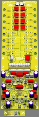
Hi All,
Sorry for the delay.
I have now made the extended version also, and prepared a production panel.
I have a bit of room in the top right corner (8.6 * 6.5 cm), what shall we put here? - I thought about maybe a front end regulator ?? let me know
\\\Jens
Sorry for the delay.
I have now made the extended version also, and prepared a production panel.
I have a bit of room in the top right corner (8.6 * 6.5 cm), what shall we put here? - I thought about maybe a front end regulator ?? let me know
\\\Jens
Attachments
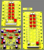
Jens, Is there enough room for the regulator and the connections from a separate transformer. We get charged mostly for board area. Any extra use of the space is better and cheaper for the constructor. I say go for it. I like those nice bright yellow boards. Tad
Front end regulator board
A regulator for the front end would be a great addition to this setup!
What is the cost for a complete panel? That might be a good way to offer them to people that are interested in both output stage types.
It might also save them some money.
Thanks,
Donovan
A regulator for the front end would be a great addition to this setup!
What is the cost for a complete panel? That might be a good way to offer them to people that are interested in both output stage types.
It might also save them some money.
Thanks,
Donovan
- Home
- Group Buys
- Jens Rasmussen Leach clone group buy