The woofer you are using is a popular replacement for the Black Widow.
The 15C also comes as a highly recommended replacement for
The Klipsch K-33 woofer used in La Scala.
Yes - just gathering the pieces of the puzzle before final assembly.🙂
My previous loudspeakers were original Altec A7-500-8.
I now have modified Klipschorns, Belles, and a LaScala. + a few DIY efforts.
My previous loudspeakers were original Altec A7-500-8.
I now have modified Klipschorns, Belles, and a LaScala. + a few DIY efforts.
Doing it acoustically would certainly be best. Having a look at the Kappa datasheets, the measured response is not too surprising. If the bass cabinet and woofer can be better tuned, that's the road to follow.
Hmm, my response was based on what I 'read' the other day with feverish mind 🙁, 'seeing' only the preponderance of an Altec A5 thread, so while still relevant in general, have no experience with other than '60s era spec Altec 416, 515, both with responses quite different to the Kappa, so not sure if the desired response can be achieved.
Still worth a try though and the XO + notch filter can tame its rising response, HF peaking.
GM
A quick sim of a mid-bass trap shows that the bass hump could be tamed and better match the woofer to the horn. I think a series trap of 3.3 mH + 100uF + 5R would work wonders to flatten the woofer response. Of course you'd have to play around with those values, but that's in the ballpark. If you made the 5R resistor one side of an L-Pad, you could dial the attenuation up and down.
Tizman. Do you have a schematic of your crossover with the actual values you used?
Tizman. Do you have a schematic of your crossover with the actual values you used?
I’m not sure how I would tune the FH-1 cabinet other than doing so through the crossover.
For clarity, I use SET amps mostly, and the last combined measurement of the raw drivers was done with one.
I posted one, but now knowing the FH-1 has a ~2:1 CR, not sure how linearly it will unload and probably too much low end lost with even just a minor leak around the driver, so while maybe worth trying out of curiosity, not real hopeful unless it just happens to work for you in combination with the XO, though can't imagine the Hiraga's component specs being of any use except as a starting point.
Factor in it's a SET measurement, meaning the driver is 'tracking' the woofer's impedance, switching to a high DF SS amp in theory rolls off both ends of its response, which again, may work in room if the speaker is in a major room null.
GM
Pano: I will draw the schematic up shortly and post it. I have several 3.6mH inductors at hand, and could put a couple of inductors in series to create 3.3mH, but 3.6mH would be much easier.
A quick sim of a mid-bass trap shows that the bass hump could be tamed and better match the woofer to the horn.
Yeah, toss enough electrical components in the signal path and sooner or later one gets the desired response, but to me it's a 'what price glory' scenario, so time for me to bow out.
GM
Glyph: I do indeed have all the parts at hand. It's very simple so I can put the bits together easily and informally to check it out. It does not have any EQ on the HF, but that may not be an issue.
Last edited:
Do you have a schematic of your crossover with the actual values you used?
Here it is. Sorry, not the prettiest drawing...
Attachments
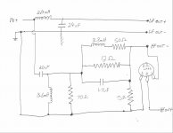

Thanks for the drawing. That's the Hiraga topology with somewhat different values. I'll have a look tomorrow. Honestly I don't think you need the the horn EQ, or at least not hat much of it. That EQ was meant for a very different horn and driver.
Thanks for the drawing. That's the Hiraga topology with somewhat different values. I'll have a look tomorrow. Honestly I don't think you need the the horn EQ, or at least not hat much of it. That EQ was meant for a very different horn and driver.
Just a quick question. If I jumper past the LCR section should I do anything with the 70 Ohm and 5 Ohm resistors to ground?
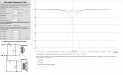
Given your crossover and the measurements, here is what I would try. It still leaves a droop in the top end of the horn, but that might sound OK. Still a small bump near 230Hz from the woofer, but that might also sound full.
If you can find something close to this, give it a listen and a measure, let us know what you think. If you want to buy parts to experiment with, don't bother with high dollar parts. Get some decent non-polar electrolytic crossover caps and you can use and iron core inductor for the woofer. Once you find the component values that work, then buy better parts.
If you can find something close to this, give it a listen and a measure, let us know what you think. If you want to buy parts to experiment with, don't bother with high dollar parts. Get some decent non-polar electrolytic crossover caps and you can use and iron core inductor for the woofer. Once you find the component values that work, then buy better parts.
Attachments

I disconnected the LCR shaping components of the Hiraga crossover as well as the the resistors to ground on the HF portion. I left the L-Pad in just in case I use the crossover with a lower sensitivity LF section. I also moved the HF horn back on the top of the LF section so that the mouth of the compression driver is 25 inches back from the front of the LF cabinet in order to time align the drivers. REW shows the frequency response to be +/- 4.5 DB for the majority of the trace, with a drop at the frequency extremes, and the sound fantastic! Compared to a pair of Klipsch Las Scala, the sound is more cohesive and realistic. The only thing lacking is the highest frequencies when I A/B the two sets of speakers. I will try the A7-500 schematic next...
- Home
- Loudspeakers
- Multi-Way
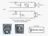
- Jean Hiraga Altec A5 Crossover modification