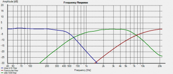
Filter Functions
This is were I ended up electrically with my passive A5 crossover. Not shown on the graph is the attenuation of the mid (~12dB) and the super tweeter (~15dB).
Of course the acoustic curves were different because of the response of each driver. Electrically the crossover points were 600 Hz and 7660 Hz.
My 288 compression drivers on the 1005 horns didn't play well up high, so I ended up rolling them off circa 8K and filling in with a Fane super tweeter.
This is were I ended up electrically with my passive A5 crossover. Not shown on the graph is the attenuation of the mid (~12dB) and the super tweeter (~15dB).
Of course the acoustic curves were different because of the response of each driver. Electrically the crossover points were 600 Hz and 7660 Hz.
- Woofer: ........416A in 828 cabinet. 8 ohm. LP 540 Hz
- Mid: ............1005 horn with 288 16 ohm HP 700 Hz & LP 7700 Hz
- Super Tweet: Fane bullet with JBL 'phram. HP 7700 Hz
My 288 compression drivers on the 1005 horns didn't play well up high, so I ended up rolling them off circa 8K and filling in with a Fane super tweeter.
Attachments
Very sorry for late reply, since travelling on work. I also had a bad luck with 16ohm drivers with 515B/288 combo.
Now that got the 416B /288 - 8 ohm want to try this.
I am bit weak in electronics and always rely on others to do the job, hence will take the help in measuring.
Hi Pano,
I do not have speaker measurement kits and yes i am willing to invest in one, since i will be doing since learning the DIY projects now.
Actually i tried ( 416B and 288G- 8 ohms) with the orginal altec crossover at 500hz/800hz/1200hz.. I have the liking at 800hz and seems to be performing to my liking.
Hence as per your active version, i believe the crossover points in-between 540 to 800HZ i should get settled in.
Will started tweaking in from this week with raw components, since i have ordered various caps and inductors to the nearest value and will be arriving this week from parts express.
Now that got the 416B /288 - 8 ohm want to try this.
I am bit weak in electronics and always rely on others to do the job, hence will take the help in measuring.
Well I did not have good luck with the published Hiraga crossover and my A5. That has always puzzled me, as I heard and loved the original that Hiraga and I built. Different drivers, I guess.
The published crossover is a staring place, but I ended up a goodly distance away from it.
Really the best way is to measure, measure, measure then build your own. Then tweak it more.
Hi Pano,
I do not have speaker measurement kits and yes i am willing to invest in one, since i will be doing since learning the DIY projects now.
Kumar - do you have a speaker measurement set-up? Or would you be willing to invest in one? That's going to be the best way to design your own crossover that is adapted to your system.
Actually i tried ( 416B and 288G- 8 ohms) with the orginal altec crossover at 500hz/800hz/1200hz.. I have the liking at 800hz and seems to be performing to my liking.
Hence as per your active version, i believe the crossover points in-between 540 to 800HZ i should get settled in.
Will started tweaking in from this week with raw components, since i have ordered various caps and inductors to the nearest value and will be arriving this week from parts express.
Good to hear from you. Yes the best way to do this is to invest in the measurement setup. A microphone, a USB soundcard, an impedance rig.
If you have a soundcard with 4 channel output, you can experiment with 2-way active. You'll need two stereo amps. For the horns, you will need only about 3-5 watts. We can help you with the the setup.
If you have a soundcard with 4 channel output, you can experiment with 2-way active. You'll need two stereo amps. For the horns, you will need only about 3-5 watts. We can help you with the the setup.
Thanks...Starting with I have a USB soundcard ( Esi Juli@ ) and will get microphone and impedance rig.
I have two stereo amps ( two no's - 2A3/45 tube amps) and no solid state.
I have two stereo amps ( two no's - 2A3/45 tube amps) and no solid state.
A quick update on my crossover. I ended up splitting the crossover into LF and HF sections, and running the split two way crossover with two stereo amps. After listening for a while, I found that the extreme top end was lacking in comparison to my La Scalas, and I reconnected the shaping portion of the network on the HF section. The bass seems to have filled in substantially with break in. I have a triode connected KT120 amp on the bass frequencies, and an El Mighty Cacahuate amp (WTFamps.com) on the high frequencies. The separate volume controls allow me to balance LF and HF, but can be a little finicky. I am very happy with the SQ. I will post a REW measurement shortly.
New measurements
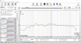
These are the REW measurements as promised.
FULL XO 1 METER is a measurement taken 1 meter from the HF horn, of the entire speaker through the crossover.
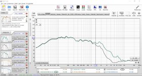
BASS AND HF CLOSE WITH XO is an overlay of measurements taken of the bass horn and of the HF horn in which the microphone was placed at the mouth of each respectively.
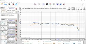
BASS XO YES NO is the bass horn measured at the mouth with with and without the crossover.
HF XO YES NO is the same thing done for the HF horn.
I am very confused about why the BASS XO YES NO photo looks the way it does. The low pass starts at around 1100 HZ rather than at the 625 HZ it is supposed to start at. If you look at the FULL XO 1 METER image, it seems that this incorrect crossover point adds to the excess of energy between 600 and 1400 HZ. The error in the crossover point may be due to using 6 Ohms as the impedance of the Eminence 15C in cabinet rather than some other value. Fixing this looks like it would even out the frequency response.
These are the REW measurements as promised.
FULL XO 1 METER is a measurement taken 1 meter from the HF horn, of the entire speaker through the crossover.
BASS AND HF CLOSE WITH XO is an overlay of measurements taken of the bass horn and of the HF horn in which the microphone was placed at the mouth of each respectively.
BASS XO YES NO is the bass horn measured at the mouth with with and without the crossover.
HF XO YES NO is the same thing done for the HF horn.
I am very confused about why the BASS XO YES NO photo looks the way it does. The low pass starts at around 1100 HZ rather than at the 625 HZ it is supposed to start at. If you look at the FULL XO 1 METER image, it seems that this incorrect crossover point adds to the excess of energy between 600 and 1400 HZ. The error in the crossover point may be due to using 6 Ohms as the impedance of the Eminence 15C in cabinet rather than some other value. Fixing this looks like it would even out the frequency response.
Attachments

Thanks for the update, Tizman.
Thanks for your help with this! A quick question. In the Hiraga schematic, which resistor can be played around with to increase and decrease the notch created by the HF filter portion? Is it R3, the 12 Ohm resistor? I tried to look at a bunch of different articles on LCR filters online to figure it out, but the extra resistors around theGHiraga schematic's LCR are confusing me.
Good morning Tizman. You're up early! 🙂
That's not a bad result to start. There is that midrange bump where the drivers overlap. It looks to me like the woofer is not rolling off fast enough. There a few things you can do to correct that, like a Zobel circuit or changing the values of the low pass filter. The woofer is going to have a rising response, so crossing lower and/or faster is need to get it to sum with the horn.
EDIT: It also appears that the horn crossover isn't doing much high pass. We should see some roll-off, ever with your sweep starting at 400Hz
I'll take a closer look today. BTW, you can use the little camera icon there in REW to export just the graph. You can also include or exclude certain things, and add labels. It's very handy.
I am very confused about why the BASS XO YES NO photo looks the way it does.
Impedance plots for both horns?
GM
Good morning Tizman. You're up early! 🙂
That's not a bad result to start. There is that midrange bump where the drivers overlap. It looks to me like the woofer is not rolling off fast enough. There a few things you can do to correct that, like a Zobel circuit or changing the values of the low pass filter. The woofer is going to have a rising response, so crossing lower and/or faster is need to get it to sum with the horn.
EDIT: It also appears that the horn crossover isn't doing much high pass. We should see some roll-off, ever with your sweep starting at 400Hz
I'll take a closer look today. BTW, you can use the little camera icon there in REW to export just the graph. You can also include or exclude certain things, and add labels. It's very handy.
Actually, I was up late. I am in the restaurant business, and COVID-19 has shut that down for the moment, but I still keep the late hours. I have a number of components on hand of different values, so I can breadboard them until I get something that works. GM mentions impedance plots for both horns, which I haven’t done and will look into. That’s probably where I should have started.
Impedance plots for both horns?
I had a quick look. I have a Umik-1 for measuring and have not used the sound card in my laptop for REW yet. It seems I need to put together a jig and use my sound card. Is this the impedance plot that you are referring to?
Yes, and I was about to ask for the impedance plots but GM beat me to it.
I do have some from my Altec A7 that I can start with. I assume you are using 8 ohm drivers?
And what about your horn plot? It does not look like there is a high pass filter. At least not the one you drew.
I do have some from my Altec A7 that I can start with. I assume you are using 8 ohm drivers?
And what about your horn plot? It does not look like there is a high pass filter. At least not the one you drew.
The HF horn is a Renkus-Heinz SSD-1800 8 Ohm in a 511B. The bass horn is an Peavey FH-1 with an Eminence 15C in it. The Eminence is a 4 Ohm woofer. From reports online, as I haven’t measured the actual impedance of the 15C/Fh-1 combo, the impedance of the 15C in a FH-1 is supposed to be 5.8 Ohms. I know what you mean when you say that neither the HF or LF crossovers seem to be doing very much. I use SET amps on both of that has anything to do with it. The thing is, if using a SETs is relevant, I will need to create a crossover that takes that into account, as I will most likely continue to use SETs.
The SET will make a little difference, but not as much as shown in your plots. Something isn't working right.
I'll see if I can find impedance plots that will start me out. I'm not familiar with the Eminence 15C. Is it the Kappa 15LFC?
I'll see if I can find impedance plots that will start me out. I'm not familiar with the Eminence 15C. Is it the Kappa 15LFC?
That’s probably where I should have started.
Yeah, pretty much. 😉
GM
I did find published impedance plots of the woofer and the R-H driver. Yours will be different because of the different horns, but it's a start.
The crossover you drew does not seem well adapted to your divers at all, but with your close measurements it can be hard to tell. Is it possible for you to do sweeps with the mic at 1M or 5 feet? No crossovers. That would help us know a little better what's going on.
The crossover you drew does not seem well adapted to your divers at all, but with your close measurements it can be hard to tell. Is it possible for you to do sweeps with the mic at 1M or 5 feet? No crossovers. That would help us know a little better what's going on.
- Home
- Loudspeakers
- Multi-Way
- Jean Hiraga Altec A5 Crossover modification