i wish i could see the waveform in action. (could be diode breakdown happening here)
just to be certain your saying the ripple voltage is 20 volts?
Try to change the rectifier diode, also, but no changes
Just want to throw in that measuring DC voltage at the bias supply point, where a high level of probably distorted audio signal is present, will not give you sensible readings.
I admit I did not read the whole thread, but I saw you have a conductive board...
Put it in the trash bin, this will not lead you anywhere IMHO.
Furthermore, are you sure your quiescent bias current is not already set too high?
Also, in a Class AB push-pull power stage, maximum power dissipation does not occur at maximum output, but rather below this point.
Sorry if you have already considered this.
Cheers,
Georg
Hello Georg, and thanks for your comment.
I tryied to set bias current also quite below 30mA, but red plating is still present.
I supposed also that something is wrong in the power grid supply circuit and replaced R24-25-31-32 and connections to the tubes but no results.
I replaced also C23 (the first filter cap) because I had a quite high ripple (4V at idle, 20V at max power). Ripple is eliminated but no changes in redplating.
Measuring at ends of the 1 Ohm resistor I use for biasing, with a signal applied at input (I know is not a real measure, but I use it as an indicator) the redplating starts when the value is 120mA and growth if I raise the input signal (no matter if this is obtained raising the input signal at High input jack, or moving CW the gain or the master volume. When the value goes beyond 120mA the tube starts redplating a little at cross of plates.
R24-25 is 150k on your other schematics, and what you have is 220k. Why not parallel another 220k? (You can later increase the capacitance of coupling cap if you wish so the freq. response stay the same). In my own test, I can plug in only one tube, I am not sure if you can do that. In this way can test and study the tube individually and isolated to one side of amplification (tube, bias, OT etc). On mine the tubes do not clip as heavily as yours, only very slight clipping as signal is increased as cross-over distortion become more prominent during clipping.
Last edited:
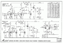
Hi Koonw. In the circuit I've 220K resistors, as indicated in a note in the foot of the Mark Huss schematic. In fact now I'm looking more to the original Marshall schematic (in attachment what I found) that indicate 220K for EL34 models.
Measuring at ends of the 1 Ohm resistor I use for biasing, with a signal applied at input (I know is not a real measure, but I use it only as an indicator) the redplating starts when the value is 120mA and growth if I raise the input signal (no matter if this is obtained raising the input signal at High input jack, or rotating CW the gain or the master volume).
When the value goes beyond 120mA the tube starts redplating a little at cross of plates, and much more if raise the input up to 200-220mA (max value I measured).
In the mean time I searching on the web about redplating and find this very interesting thread on Metropoulos forum: redplating 1959 w larmar - Metropoulos Forum
There are a lot of things I haven't the knowledge to understand exactly , but there a couple of comments of Randall Aiken about the too high voltage we apply to the power tubes and the fact that this situation force the tube to work in a critical area where redplating could happen more easily. In fact I observe that all my voltages on B+ are quite higher than the original Marshall ones (see attachment).
Thare are also a couple of suggestions in that thread:
- try to test with a load of 16 Ohm but with the selector on 8 Ohm --> no results, redplating still the same
- try to reduce to around 400Vdc the B+ value (at the moment I've around 460Vdc).
What do you think about? Can you suggest a simply way to make this test (it's enough a resistor in series)? Thanks for your comments and helps.
Attachments
Before you can verify anything more on red plating first you should make very sure that the 2 tubes work together nicely, i.e. you should verify with triangular waveform as I mentioned early, not into clip but at normal power output.
Food for thought: Why you amp clipping so heavily, is it normal? It's guitar amp I know clipping maybe part of the design. If the output continue to clip this means it's allow continue to be able being driven. That is not very good ( a good cause for red plating) IMO. So has the bias sag too during clipping? Normally if the bias is maintained at say -40V, it should stay there, otherwise (esp if lowered or sag) it just asking for trouble (such continued to be able to driven and getting more susceptible with higher HT). Lower the voltage may stop red plate maybe only part of the story, not harm trying.
Food for thought: Why you amp clipping so heavily, is it normal? It's guitar amp I know clipping maybe part of the design. If the output continue to clip this means it's allow continue to be able being driven. That is not very good ( a good cause for red plating) IMO. So has the bias sag too during clipping? Normally if the bias is maintained at say -40V, it should stay there, otherwise (esp if lowered or sag) it just asking for trouble (such continued to be able to driven and getting more susceptible with higher HT). Lower the voltage may stop red plate maybe only part of the story, not harm trying.
Last edited:
try to reduce to around 400Vdc the B+ value (at the moment I've around 460Vdc).
What do you think about? Can you suggest a simply way to make this test (it's enough a resistor in series)?
You can control the tube current more easily by reducing the screen voltage so you can keep the plate voltage high. Try to reduce screen voltage with a series of Zener diode, step of 5V or so say.
Before you can verify anything more on red plating first you should make very sure that the 2 tubes work together nicely, i.e. you should verify with triangular waveform as I mentioned early, not into clip but at normal power output.
Food for thought: Why you amp clipping so heavily, is it normal? It's guitar amp I know clipping maybe part of the design. If the output continue to clip this means it's allow continue to be able being driven. That is not very good ( a good cause for red plating) IMO. So has the bias sag too during clipping? Normally if the bias is maintained at say -40V, it should stay there, otherwise (esp if lowered or sag) it just asking for trouble (such continued to be able to driven and getting more susceptible with higher HT). Lower the voltage may stop red plate maybe only part of the story, not harm trying.
Here the results of the test with triangular waveform - 100mVpp at High gain input. The scope picture:

Controls was
- Presence&Bass = 10
- Middle&Treble = 0
- Master & Gain = 3 (no redplate with this combination)
At PI output (after the coupling caps) I measured 50Vpp both for V4/V5 signals. here the pictures:


I take also the scope picture at pin 3 of both tubes V4/V5. Here the pictures. The scale is 10V.


I measured also the Bias sag. At idle the bias voltage is -36Vdc, at full power (master & gain = 10) is -41Vdc. The replacement of C23 improved a lot the situation. Before at full power I had a B+ ripple of 20Vdc (now eliminated) and the Bias voltage at maximum power drops to -58Vdc (may be the 2 values are related?)
Can you adjust the image so that the zero crossing line of the plot is in horizontal middle (centre) line of the screen, we use this middle line as reference.
Pin 3 is plate, do you mean pin 5, grid 1?
I take also the scope picture at pin 3 of both tubes V4/V5. Here the pictures. The scale is 10V.
Pin 3 is plate, do you mean pin 5, grid 1?
Last edited:
if it is the plate, what's up with the late conduction in the top trace in the last set of pictures?
if it's the grid why do the waveforms look different than the previous set of pictures (output of phase inverter)
if it's the grid why do the waveforms look different than the previous set of pictures (output of phase inverter)
also this may be just me... but if a negative voltage increases it become more negative...
what i find bizzarre is that as the amp is driven harder the less gain the output has (if i'm correctly understanding SimoS description)
what i find bizzarre is that as the amp is driven harder the less gain the output has (if i'm correctly understanding SimoS description)
It's plate, between pin 3 and ground. I don't know if it's significant.
Ok, the 2 waveforms should look more or less very similar to each other and not so distorted, unless it's due to NFB correction. If so much correction is needed you have distortion somewhere (tubes?). I suggest you get another pairs of tube to compare.
Or remove the NFB to see if distortion now appears in the output and measure again, the pin 3.
Last edited:
- Home
- Live Sound
- Instruments and Amps
- JCM800 2204 Phase Inverter issue and other