Getting back to the puzzle Mark left for me:
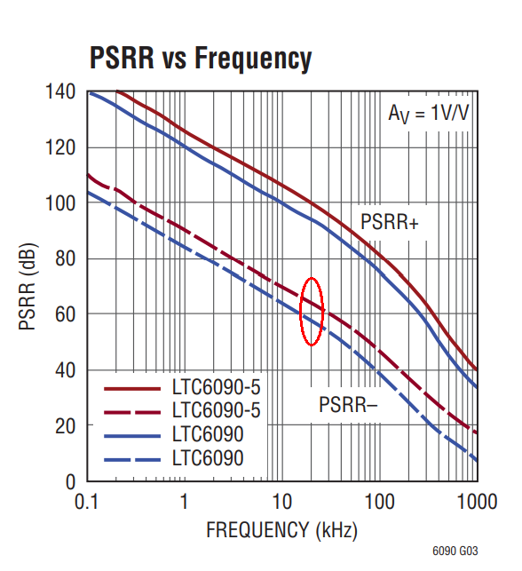
This chart says (to me) that the opamp I'm using in my FE shunt regulator has poorer noise rejection on its negative supply than its positive supply.
Mark also gives the hint:
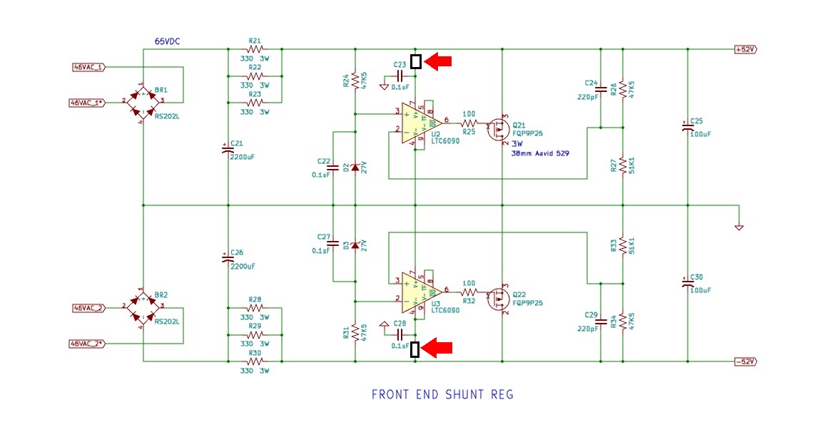
I'm not sure if those are "put something here" boxes, or ISO resistor symbols. But the location has me stumped too. The box is shown on the positive supply of the positive regulator's opamp, and on the negative supply of the negative regulator's opamp.
Perhaps Mark didn't notice that the positive and negative regulators are not symmetrical?
But even if they were, I'm not sure what this addition would do....
This chart says (to me) that the opamp I'm using in my FE shunt regulator has poorer noise rejection on its negative supply than its positive supply.
Mark also gives the hint:
I'm not sure if those are "put something here" boxes, or ISO resistor symbols. But the location has me stumped too. The box is shown on the positive supply of the positive regulator's opamp, and on the negative supply of the negative regulator's opamp.
Perhaps Mark didn't notice that the positive and negative regulators are not symmetrical?
But even if they were, I'm not sure what this addition would do....
Jeff,
Take it from me, you are way ahead of many so called High -End designs...........🙂
Take it from me, you are way ahead of many so called High -End designs...........🙂
Attachments

Last edited:

G'day mate ..................you don't get this a Maccas............Bonza! 😀
Jam
Jam
Attachments

Last edited:
On your shunt regulator either throw a 33,000uF cap after the input resistor on each rail, alternatively and probably even better you could build up the total resistance at the input of the shunt with CRCRCRCRC, eg 2200uF, 27Ohms, 2200uF, 27Ohms, 2200uF 27 Ohms, 2200uF, 27Ohms, 2200uF
That should improve things significantly, once you have implemented that the PSRR of your opamps will no longer even matter, ie you will have eliminated any issue in the performance of the opamps being a problem.
That should improve things significantly, once you have implemented that the PSRR of your opamps will no longer even matter, ie you will have eliminated any issue in the performance of the opamps being a problem.
Last edited:
I'm not sure if those are "put something here" boxes, or ISO resistor symbols. But the location has me stumped too. The box is shown on the positive supply of the positive regulator's opamp, and on the negative supply of the negative regulator's opamp.
..
RC Filtering is what he is most likely referring to, but you should also use CRCRCRCRC at the input as mentioned in my post above
Jeff, make a few assumptions and use them to do a few calculations, to figure out how good your power supply needs to be. Then design to that target. Boom, done.
Someone (not you, just a hypothetical strawman example hobbyist) might, for example, assume that their power supply needs to be constant and ripple free and noise free enough, that the supply imperfections, times the signal handling circuit's PSRR, is less than or equal to (2 to the power -18). The supply-created imperfections in the signal circuitry's output, are the same magnitude as one LSB of an 18-bit D-to-A. {my calculator claims that equals 3.8 parts per million.} Now this "someone" can work backwards to find out how good his supply must be. Design to that target, slather on some extra safety margin if possible, Boom. Done.
Someone (not you, just a hypothetical strawman example hobbyist) might, for example, assume that their power supply needs to be constant and ripple free and noise free enough, that the supply imperfections, times the signal handling circuit's PSRR, is less than or equal to (2 to the power -18). The supply-created imperfections in the signal circuitry's output, are the same magnitude as one LSB of an 18-bit D-to-A. {my calculator claims that equals 3.8 parts per million.} Now this "someone" can work backwards to find out how good his supply must be. Design to that target, slather on some extra safety margin if possible, Boom. Done.
I tried these two ideas out: RC filtering on the opamp supply, and CRCRC pre-filtering.
RC filtering on the opamp is interesting. Sticking with a C0G cap you can't really get enough of a filter to make any difference. Moving to an X7R allows for an improvement of a bit over 2dB at 300kHz. Using a tantalum doesn't help as the ESR takes away everything the increased capacitance gives. A big film cap can produce significant results (in the region of 10dB).
Moving on to pre-filtering, the opamp doesn't like CRCRC (or CRC) filtering (it puts a big spike in the attenuation curve). CRCR does produce a huge win, increasing the attenuation by something like 50dB(!).
This begs the question that while this is all interesting (and instructional), is it material? Will there be any audible difference between 75dB and 125dB of attenuation at 20kHz? I know it's not much of a bar, but the venerable L78XX can't even get within a country mile of the 75dB spec.
(Mark posted after I had written this, so I'm now off to do his suggested math....)
Once you get below 1uV of ripple at the ouput of amp then the job is well and truly done as far as I am concerned.
For me output impedance of the powersupply is what I usually am more focused on. I want better than 0.01 Ohms
For me output impedance of the powersupply is what I usually am more focused on. I want better than 0.01 Ohms
Did you also try
2200uF, 22R, 2200uF, 22R, 2200uF, 22R, 2200uF, 22R, 2200uF, 22R
Or do you need more than 22 Ohms of resistive loading feeding into the shunt?
Either way, I am guessing the ripple on the supply is probably not really going to be a problem.
2200uF, 22R, 2200uF, 22R, 2200uF, 22R, 2200uF, 22R, 2200uF, 22R
Or do you need more than 22 Ohms of resistive loading feeding into the shunt?
Either way, I am guessing the ripple on the supply is probably not really going to be a problem.
For me output impedance of the powersupply is what I usually am more focused on. I want better than 0.01 Ohms
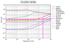
About half of the competitors in the Linear Audio "shootout" achieved 0.01 ohms at 20 kHz. And about half did not.
_
Attachments
OK, Mark's LSB (out of 18) is 54dB. So let's add 11 ('cause my volume control goes to 11) and say I want my regulator-attenuation + amp-PSRR to be 65dB. If my regulator's attenuation is 75dB, then my PSRR can be... well, completely non-existent.
Now to measure output impedance.
SPICE says my FE/VAS draws 96mA +/- 3mA. If I put that load on the regulator (at 20kHz), then I get a 20kHz PtP ripple of 38uV. R = V/I so my effective output impedance (assuming I've done this right) is 0.038/6 or 0.006 ohms. Whoo hoo!
I look pretty good on the Linear Audio chart, too, though I suspect most of those were far more efficient than my paltry 37%. (Fortunately for me this is the Pass forum and none of us are afraid of a little heat. 😎)
I also measured at 1K and my curve follows the two Jung regulators. I couldn't measure any lower than that because SPICE runs out of dynamic range.
Jeff you did the math incorrectly.
2 raised to the power (-18.0) equals 10 raised to the power (-5.419). Since we're talking about voltage not power, that's (20 * -5.419) = -108.4 dB.
A nice aid to memory is: -120dB is 1ppm. -100dB is 10ppm.
Since we're talking about 4 ppm, the number of dB must be somewhere between -120dB and -100dB. And it is. Double check: yes!
So the 20log(x) vs 10log(x) is voltage vs. power?
So I need on the order of 45dB PSRR in the FE. Off to research how to calculate that....
So I need on the order of 45dB PSRR in the FE. Off to research how to calculate that....
- Home
- Amplifiers
- Pass Labs
- JamJar: an HPA-1-inspired power amp