Consider doubling or tripling the resistance values of the gate resistors on the laterals if you need to improve amp stability or reduce bandwidth.
Allow room on the pcb for the addition of gate resistors on the Toshiba mosfets, simply use links if not required.
Allow room on the pcb for the addition of gate resistors on the Toshiba mosfets, simply use links if not required.
Last edited:
Pico,
In my experience that with this topology eliminating R19 and C10(Zobel network) will almost cause this circuit to oscillate, degenetating the VAS might help like you suggest but then again you might know something I don't. 😛
As far as as source resistors I would suggest about 0.15ohm if you cant get a tight match.
I still maintain that VAS is the Archilles Heel of the circuit and can be improved but then again I don't base my designs on measurements alone......
Jam
I think I would run output stage free of any negative feedback, that should guarantee stability, and just keep adding pairs of mosfets to get the required damping factor.
I think the output MOSFETs' quiescent current will vary a fair bit, depending on how stable that V4 and V5 is and how hot the MOSFETs are... I also believe that the DC offset will hunt a fair bit.
But, I might be wrong...
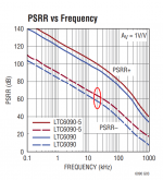
V4 and V5 should be rock-steady:
... but I think I'll still go back to using a TL431 as a bias spreader.
Cheers,
Jeff.
Attachments
Pico,
In my experience that with this topology eliminating R19 and C10(Zobel network) will almost cause this circuit to oscillate, degenetating the VAS might help like you suggest but then again you might know something I don't. 😛
...
OK, I need some schooling. The VAS degeneration is supposed to linearize the Id, at the expense of some gain, right?
Pico suggests reducing (or even eliminating) it. Is the idea that more gain will give me more NFB, which will be more advantageous than the local feedback (linearization) I'm losing?
And when Jam mentions Pico's suggestion, does he really mean de-degenerating? (That comment was in relation to possibly allowing the removal of the Zobel network. Would that be because the increased NFB makes the amp less likely to oscillate?)
Thanks, guys. I am learning. 🙂
One last question regarding the VAS being the Achilles Heel:
...enough so that the current-mirror version would be better?
Thanks again,
Jeff
PS: I know the right way to find out would be to listen to a bunch of different permutations -- but it's a hobby and I enjoy building stuff more than doing comparative listening. 😉
...enough so that the current-mirror version would be better?
Thanks again,
Jeff
PS: I know the right way to find out would be to listen to a bunch of different permutations -- but it's a hobby and I enjoy building stuff more than doing comparative listening. 😉
Eliminating degeneration on the vas will reduce many of it's weaknesses.
If you're not interested in using localised cascode feedback, I would then use degeneration on the input jfets with a 20 Ohm trimpot. This will be extremely useful in tuning the amp to explore what sounds good to your ears.
Resistive load of the vas stage is also a good idea to help get the character you want. It also helps linearise the load the vas stage sees. 1k to 2k is probably a good place.
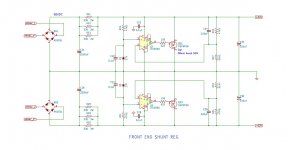
Bias the vas stage around 100mA or so, somewhere near it's 0 temp coefficient. That's assuming you're going the zero degen route on vas. Obviously still leave a place for degenerating resistors on pcb, just use links.
Leave a place on the pcb to add the zobel network. Try with and without.
Laterals have a notorious reputation for being unstable, having options on the pcb is never a bad thing.
You definitely want the ability to tune the amp to your ears otherwise you'll probably end up with an amp that sounds ok, but will get boring real quick like many other amps out there.
If you're not interested in using localised cascode feedback, I would then use degeneration on the input jfets with a 20 Ohm trimpot. This will be extremely useful in tuning the amp to explore what sounds good to your ears.
Resistive load of the vas stage is also a good idea to help get the character you want. It also helps linearise the load the vas stage sees. 1k to 2k is probably a good place.
Bias the vas stage around 100mA or so, somewhere near it's 0 temp coefficient. That's assuming you're going the zero degen route on vas. Obviously still leave a place for degenerating resistors on pcb, just use links.
Leave a place on the pcb to add the zobel network. Try with and without.
Laterals have a notorious reputation for being unstable, having options on the pcb is never a bad thing.
You definitely want the ability to tune the amp to your ears otherwise you'll probably end up with an amp that sounds ok, but will get boring real quick like many other amps out there.
Last edited:
Haha! Starting to look like Pico and Jam have some different experiences which lead them to go in somewhat different directions.
Jeff said
One last question regarding the VAS being the Achilles Heel:
...enough so that the current-mirror version would be better?
In my humble opinion yes but the current mirror version need work (for you application) which leads us back to the other options...........🙂
De-generation would increase you open loop bandwidth at the expense of available feedback . The question to be asked is how much feedback do you need and what is the downside to too much feedback .........feedback is sometimes a convenient band-aid.
Attachments

Last edited:
Haha! Starting to look like Pico and Jam have some different experiences which lead them to go in somewhat different directions.
Just things to try.
I have tubes of exicon laterals that are virtually identical to one another, matching has been easy with those parts for me, I’ve never needed to add degenerating resistors to prevent current hogging. I have no experience with original Hitachi laterals, they could be a different story.
Last edited:
The original Hitachi lateral Mosfets that were used in the Hafler DH-200, DH-220 and others were matched by Hafler and marked with numbers from 1 to 5. The resulting matched pairs and triplets were used without any source resistors. Bias current was set at 125 mA per device at the factory, or as recommended in the kit building instructions.
Mark,
............here are several ways to skin a cat, and pico's ideas might be correct in the context of what he is trying to achieve and I admire the fact that he has spent the time to try out these different topologies but in the end I assume once the topology is chosen we try these ideas to see what sounds best.
Jam
Granted you can operate laterals without source resistors but sometimes it is not so easy in the diy arena because the population of devices you need to get a match and the problems of testing the devices correctly.
I used to own a Hafler mosfet testing jig which I gave to Nelson Pass. I stopped using laterals for outputs because of their limitations in my application.
Tungsten has made a good point that is sometimes ignored , it is much better to match devices a the bias current(and if possible voltage) as used in their application.
Jam
Last edited:
Tungsten has made a good point that is sometimes ignored , it is much better to match devices a the bias current(and if possible voltage) as used in their application.
Jam
I match over the entire Id vs Vgs curve at the operating voltages and operating heatsink temperatures.
I am constantly surprised even shocked how good these devices match.
pico,
I will have to try them if they are as good as you say. How close is the P channel compared to the N? If they are, your suggestion of using them outside the feedback loop should work, my main concern is the low tranconductance but I suppose if you use enough devices in parallel you might have something. I found the Hitachi's problematic in several areas.
Jam
Unfortunately the P is not close to the N, but you know how to get around those issues.
Papa always teaches us to think outside the box, I know you know of many interesting ways to create symmetry or asymmetry in the output stage.
I wish I was home to share my recorded measurements.
I sent Papa an email once with the details of how many devices it would take to achieve really decent output impedance without negative feedback. It certainly wasn’t a ridiculous number.
I think it was based on double die laterals.
I’ve been away from tinkering for quite a while, but now you guys got me excited again.
Last edited:
Hi Jeff,
Unless your matching is very tight I would use small source resistors for the output devices.
I would use larger gate resistors for the outputs (safety)
Add protection zeners from gate to source.
The weakest part of the circuit is the VAS.
I still would use a Vbe multiplier for the bias circuit as apposed to the resistor.
Jam
P.S. Where is pico when you need him .............
Hi Jam,
have a look at the data sheets. These LatFETS have zeners bult in, besides they are varying resistances with bias voltage, a small resistance added would have no purpose at all. The gate resistors should be calculated, Vbe multipliers are not necessary, these are not HexFETS. They where specifically designed for audio not anything else. I have developed many amplifiers using them since they became available, both for myself and others. In fact they are my favourite output stage because of their ease of use🙂
Last edited:
So far, this is my favourite thread, because the pros & cons of design ideas are being discussed, very educational, I wish there where more threads like this; much appreciated, thank you gentlemen.
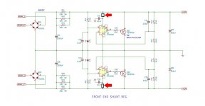
Took a whack at cascoding the push-pull VAS. It required compensation, but it worked much better than my attempt at cascoding the single-ended one.

Better? Worse? Just different?
Cheers,
Jeff.
PS: I also tried it with a BJT VAS, but couldn't stabilise it.
Better? Worse? Just different?
Cheers,
Jeff.
PS: I also tried it with a BJT VAS, but couldn't stabilise it.
Attachments

- Home
- Amplifiers
- Pass Labs
- JamJar: an HPA-1-inspired power amp