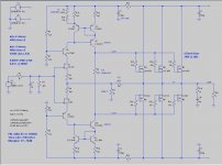
The whole output stage bias arrangement (D1, D3, M1, M2) gives me the willies. The voltage dropped across D1 and D3 is known and repeatable. But the Vgs_th values of M1 and M2 are unknown and highly variable. I suppose Hitachi, as a semiconductor manufacturer, could measure, and sort, and cherry-pick the ones which happen to have just zackly the right Vgs_th voltages. But normal people? Hobbyists? It gives me the willies.
BTW, I expect about 1200 microamperes flowing in R8, not 500 as written (?)
BTW, I expect about 1200 microamperes flowing in R8, not 500 as written (?)
^This
The lateral Mosfets certainly have a lower threshold Vgs, but not 0.65V. I would have expected to see some sort of bias spreader, even if it's a simple Vbe multiplier using an appropriate NPN transistor.
The lateral Mosfets certainly have a lower threshold Vgs, but not 0.65V. I would have expected to see some sort of bias spreader, even if it's a simple Vbe multiplier using an appropriate NPN transistor.
I have only looked at the circuit on your opening thread. You do not need Q11 and associated parts. A single resistor could set the bias. Lats do not thermally run away, as temperature increases their resistance increases. In many of my designs I used a single diode to bias at optimum current for lowest THD, which is a round 100 mA.
Hi Mark,
Did you calculate this? I don't know how to, so the 0.5mA is a SPICE measurement. Is SPICE yanking my chain again?
....
BTW, I expect about 1200 microamperes flowing in R8, not 500 as written (?)
Did you calculate this? I don't know how to, so the 0.5mA is a SPICE measurement. Is SPICE yanking my chain again?
Hi Jeff,
Regarding the Hitachi topology.
1) You need to add drivers the the output stage.
2) Current source the differential.
3) Improve the mirror
4) Plus a few other tweaks.
.......something Einstein said about making something simple but not too simple. 😀
I did mention that you have to be cautious about stability but the effort should be worth it.
I think you have several good topologies to choose from. 🙂
Jam
Attachments

Last edited:
...I don't know how to...
Just posted this in the wrong thread 😱 too many pages open.
There is probably a better way but...
+V - Q1 vbe ~23.5V
23.5V / R15 = 500uA
250uA * 3K3 = 0.825V
0.825V - Q5 vbe (call it 0.625V) = 200mV / 2K2 ~= 90uA
Meanwhile back at the farm....
Hi Jeff,
We are waiting on the edges of our seats for your desicision on the choics of front end for the JamJar.
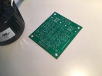
Meanwhile I am working on the next headphone amplifier (HPA-2? 😉 ).
Picture of the prototype of the gain module board , minus devices, bias circuit and servo ( which could be adapted for a power amp.)
Jam
Hi Jeff,
We are waiting on the edges of our seats for your desicision on the choics of front end for the JamJar.
Meanwhile I am working on the next headphone amplifier (HPA-2? 😉 ).
Picture of the prototype of the gain module board , minus devices, bias circuit and servo ( which could be adapted for a power amp.)
Jam
Attachments
Last edited:
...well if you are going to stay. 😀
Jam
Jam
Attachments

Last edited:
Awesome map. While I've been transplanted to Ireland, I come from the land of skiing and marijuana. 😉
Still noodling my front-end options for JamJar. For Beefcake I'm going with the single-JFET LTP with BJT CCS. (There may even end up being 3 contestants in the ring.)
Got my pumpkin pie made, and the stock for the gravy. Turkey is brining. (We do Thanksgiving on Saturday since people don't get Thursday & Friday off here.)
Cheers,
Jeff.
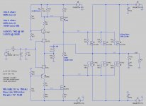
I took another run at the push-pull VAS and this time managed to make it behave.
It has slightly more complexity due to needing a split supply, but also runs the output devices slightly cooler because of it. Other than that, it produces very similar performance numbers as the current mirror version.

It has slightly more complexity due to needing a split supply, but also runs the output devices slightly cooler because of it. Other than that, it produces very similar performance numbers as the current mirror version.
Attachments
I think the output MOSFETs' quiescent current will vary a fair bit, depending on how stable that V4 and V5 is and how hot the MOSFETs are... I also believe that the DC offset will hunt a fair bit.
But, I might be wrong...
But, I might be wrong...
Hi Jeff,
Unless your matching is very tight I would use small source resistors for the output devices.
I would use larger gate resistors for the outputs (safety)
Add protection zeners from gate to source.
The weakest part of the circuit is the VAS.
I still would use a Vbe multiplier for the bias circuit as apposed to the resistor.
Jam
P.S. Where is pico when you need him .............
Attachments

I have found being fearless with laterals is actually a very trivial matter.
Getting closely matched parts with laterals is easy compared with traditional mosfets.
Then you have the temperature coefficient that works in your favour, current hogging never actually happens in practice, provided the person doing the matching is not a complete melon head.
I vote in favour of being a DIYFAB.
Having said that it doesn't hurt to add space for degenerating resistors. You just install links instead of resistors.
I would load the output of the voltage gain stage, eg maybe 1k to ground.
I would also change R12 and R14 to 1 Ohm or eliminate altogether.
Try and eliminate R19 and C10.
Try and eliminate R19 and C10.
Last edited:
- Home
- Amplifiers
- Pass Labs
- JamJar: an HPA-1-inspired power amp