Do you want a place to sit OR good sound?
Hi ODougbo,
"...AND it makes a good stand up vacuum cleaner! "
How about 2 or more with hinges as a room divider 🙂.
Regards,
what sort of price do you think you could ship 2 of those mcm subwoofers to the uk for ? including the price of the subsDo you want a place to sit OR good sound?
I had a chance to listen to this all weekend, it's a winner. The bass might be a bit stronger than the other 3, maybe because the mouth/woofers are tight into the corner.
Interesting though, I don't feel the box vibrating.
With those "feet" on the box. How would it change the output if you made the curve the other way so it was like a horn curve, if that makes any sense.
eg if you had made the feet with the pieces left over from the cuts of the current feet? Are you totally confused yet?
Hi Etocynned,
Generally, you want the duct to end abruptly, a horn like extension would alter the design.
In Hornresp you can simulate your modification by using the old Hornresp Input screen, changing TH into TH1, adding S4/S5, setting L45 to Exp and entering the length of "horn" you want to add.
Regards,
Generally, you want the duct to end abruptly, a horn like extension would alter the design.
In Hornresp you can simulate your modification by using the old Hornresp Input screen, changing TH into TH1, adding S4/S5, setting L45 to Exp and entering the length of "horn" you want to add.
Regards,
I have the "cut off pieces" seen in post 307. I may use them for the other tall "thin" box and lay it down.
Btw, the tall box here only has a 9" x 21" size footprint; shoebox size (o;
Btw, the tall box here only has a 9" x 21" size footprint; shoebox size (o;
With those "feet" on the box. How would it change the output if you made the curve the other way so it was like a horn curve, if that makes any sense.
eg if you had made the feet with the pieces left over from the cuts of the current feet? Are you totally confused yet?
Hi ODougbo,
"...does pointing the mouth down toward the floor meet the "end the duct abruptly" rule?"
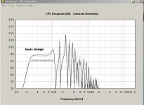
You are providing sufficient clearance that I think you are not changing the basic design. According to Hornresp a small "horn-like" extension of the duct would result in a small boost of the very lowest frequencies, and a minimal reduction in the middle of the passband. Or in other words: negligible.
The room, and the location in the room will have a much bigger impact.
I'll attach a quik look at the subject in Hornresp (these are not the exact numbers from the drawing, but I think close enough for an example):
Regards,
"...does pointing the mouth down toward the floor meet the "end the duct abruptly" rule?"
You are providing sufficient clearance that I think you are not changing the basic design. According to Hornresp a small "horn-like" extension of the duct would result in a small boost of the very lowest frequencies, and a minimal reduction in the middle of the passband. Or in other words: negligible.
The room, and the location in the room will have a much bigger impact.
I'll attach a quik look at the subject in Hornresp (these are not the exact numbers from the drawing, but I think close enough for an example):
Regards,
Attachments
Thanks Oliver (very cool) I would have to think the sound radiates out from both sides like a swashed donut. I thought about legs, but that seems to be a insignificant issue.
I'm on the fence about a second "tower", appears to me that it is a good deal/plan. The next one, the stiffer between the woofers will be a one piece "T". *&^%$#@#(
Thread1, they weight a lot, would cost wayyy to much to ship them (MCM 8"s). I'm not sure what do with them anyway. I remember a project using them in 1/3cf cab, with a 10" PR. maybe someday I'll build a test box and try that :-/
*also, new and 10 year old ones are all mixed together, hard to figure out whats whats now.
Hi ODougbo,
There are a number of nice projects for the 55-2421. The ones that come to mind immediately are jbell's FLH, Danley's TH-SPUD, littlemike's TH. They like to be in horns I guess.
Regards,
There are a number of nice projects for the 55-2421. The ones that come to mind immediately are jbell's FLH, Danley's TH-SPUD, littlemike's TH. They like to be in horns I guess.
Regards,
no worries, im looking at the matching q acoustics 2070 subwoofer, then after some time take the sub's out of it and the amp and do something really nice with it, the subs looks amazing from itThread1, they weight a lot, would cost wayyy to much to ship them (MCM 8"s). I'm not sure what do with them anyway. I remember a project using them in 1/3cf cab, with a 10" PR. maybe someday I'll build a test box and try that :-/
what do you mean, what happend with the new sub ?2009thread1...what happened?
what do you mean, what happend with the new sub ?
Yep, that's what he's asking about. Inquiring minds want to know 😛
lol no problem, i wasnt sure what you were asking about.Yep, that's what he's asking about. Inquiring minds want to know
so ive had the new sub for a week now, sounds really good, the 170mm drivers have a lot of xmax on them, im still trying to get hold of the parameters of them.
i got hold of q acoustics and i can buy the drivers from the subwoofer for £70, maybe they'd fit nice into a new enclosureYep, that's what he's asking about. Inquiring minds want to know
Hi 2009thread1,
Post #336: "...the 170mm drivers have a lot of xmax on them, im still trying to get hold of the parameters of them."
Maybe you can measure the T/S parameters, that way one could actually design an enclosure for this woofer?
Regards,
Post #336: "...the 170mm drivers have a lot of xmax on them, im still trying to get hold of the parameters of them."
Maybe you can measure the T/S parameters, that way one could actually design an enclosure for this woofer?
Regards,
i could, but i have no idea how to lol, im pretty sure i can get them sent to me by q acoustics or the supplier of the subwooferPost #336: "...the 170mm drivers have a lot of xmax on them, im still trying to get hold of the parameters of them."
Maybe you can measure the T/S parameters, that way one could actually design an enclosure for this woofer?
Regards,
__________________
Oliver
2009thread1...what happened?
Yep, that's what he's asking about. Inquiring minds want to know
so ive taken the two 6.5" qtx woofers out of my tapped horn, i was thinking of doing an isobaric design, back to back in a small/medium sized box.Hi 2009thread1
does the box have to be a certain size for these if they're sealed, or can i port it as well ?
- Status
- Not open for further replies.
- Home
- Loudspeakers
- Subwoofers
- Isobaric - less then $20