phase_accurate said:
The difficulty lies in the finding of a scheme that is suitable for mass-production - which has to take performance and manufacturing cost into consideration.
Regards
Charles
Completely agree with Charles, Yes when some firm opt for Mass-Production, its main consideration lies into Stability performances, Drifts incurred, Component Tolerances & their subtitutes all of them play an advently important role....
K a n w a r
SSassen said:Hi Jaka,
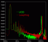
The UcD amplifier I used has slightly less gain than the two others, but at the time of these measurements that's not the of any concern, I was looking at the behaviour with different loads attached, so that's why the plot is slightly lower than the others, that's it.
Cheers,
Sander Sassen
http://www.hardwareanalysis.com
Have you checked these amps with Highly reactive loading in Midband frequencies especially with Vocal Signals not the usual Sinewaves...Then you could encounter a real time difference...
K a n w a r
Hi,
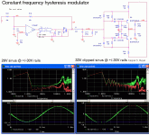
I have finally found ( searching in half a meter high pile of old papers) quite an old patent (1992) for constant frequency hysteresis oscillator. It is US 5160896 and as far as I can remember it simulates quite well. It is also a bit simpler than one proposed by analogspiceman, although it requires a multiplier.
Another interesting solution to this problem is US 6107875 , although IIRC (from simulation again) soft clipping is nor so soft as it is described in the patent.
Finally, it woud be nice if moderator would move posts (onward from post #97) regarding post or pre filter feedback into appropriate thread (that was open just for that occasion).
Best regards,
Jaka Racman
Jaka Racman said:
I have finally found (searching in half a meter high pile of old papers) quite an old patent (1992) for constant frequency hysteresis oscillator. It is US 5160896 and as far as I can remember it simulates quite well. It is also a bit simpler than one proposed by analogspiceman, although it requires a multiplier.
Hi Jaka,
Of course the method of that patent (with regard to the use of the difference between the output and supplies) is basically the same as the LTspice file I posted previously (it has to be - the math is the same).
The difference is that the control mode of the circuit of the patent is voltage rather than current and also does not feed forward the derivative of the changing current, so it is not as accurate. - a.s.
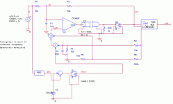
I can do it without a multiplier. The circuit does exactly the same as an multiplier would have done.
I made this yesterday. I took a whole day to figure something out that worked fast enough and with a high modulation index. The schottky diodes (bas70) was the solution.
What do you think.
I made this yesterday. I took a whole day to figure something out that worked fast enough and with a high modulation index. The schottky diodes (bas70) was the solution.
What do you think.
Attachments
This is what the mathematical model looks like. The performance of the two are identical.
BTW. The frequency is actually not constant. I incresses and then it falls a bit as function of modulation. I decrease the hysteresis voltage proportional with the modulation index. In a normal hysteresis modulator the frequency falls by 1-M^2. This indicates that the hysteresis voltage shouldn't decrease as a dicret function of modulation in a real constant hysteresis modulator.
Fainally the delay messes things up a bit.
Attachments
Originally posted by sovadk
I can do it without a multiplier. The circuit does exactly the same as an multiplier would have done.
I made this yesterday. I took a whole day to figure something out that worked fast enough and with a high modulation index. The schottky diodes (bas70) was the solution.
What do you think?
I think it looks promising. 🙂 At least at first blush, it seems to be realizable, repeatable and reasonably accurate for the application.
Originally posted by sovadk
This is what the mathematical model looks like. The performance of the two are identical.
BTW, the frequency is actually not constant. It increases and then it falls a bit as function of modulation. I decrease the hysteresis voltage proportional with the modulation index. In a normal hysteresis modulator the frequency falls by 1-M^2. This indicates that the hysteresis voltage shouldn't decrease as a discrete function of modulation in a real constant hysteresis modulator.
Finally the delay messes things up a bit.
Also, a fast moving input that changes significantly during the switching period can be a source of error (one that can be nulled - to a first order - by summing in an appropriate di/dt term).
By quasi-integrating switching stage output voltage, your circuit generates an analog of inductor current. But it tracks neither the low frequency (i.e. dc) part of current nor current shifts due to inductance changes (e.g. saturation), so it is useless for current limiting and/or overcurrent protection. It is extremely simple, however, and probably good enough for many applications. 🙂
Rather than compensate the plant by inferring its state, I favor going to the trouble to observe its actual state and using that for compensation. That way, when things limit, saturate, or otherwise go nonlinear, errors don't build up between the actual plant state and its analog (no rail sticking, etc.). That is one of the subtle advantages of leapfrog control. (Did you ever read that thread?)
Earlier in this thread, I compared Bruno's circuit to its closest linear counterpart as a function of modulation depth. At low levels the two were identical, but, near the rails, nonlinear effects (in no small part due to frequency droop) caused significant errors. I don't know how audible such behavior is, but it would be very interesting to see if any other class-d topology could do better. A combination of constant frequency hysteresis and leapfrog control might be a good candidate for such a contest (I have a feeling that just the leapfrog method combined with UcD style phase shift control might do noticeably better in this regard - maybe this weekend, eh?).
Anyway, glad to see a fellow "control freak" here on this forum. The subject is fascinating (at least to me).

By the way, do you know why Søren Poulsen seemingly dropped out of this forum? (I really was hoping to hear his take on the plusses, minuses and inner workings of AIM.)
Regards -- analogspiceman
I don't know anything about Søren Poulsen however I talked to Michael A. E. yesterday. Apparently there was some distortion problems associated with getting the frequency to be reallly constant. I've expreinced the same in a simulation I did the other day, with a scheme somewhat the same.
About the hysteresis voltage. A non symetrical, peice weise changing (and what ever you could think off as possibilly bad things), dosn't really add any distortion to the whole circuit. I con't tell you why, but that's my experince working with this circuit yesterday.
The actual modulator should of course include the output filter and it's current. This is just for easy testing. I've been using a Mueta like topology for my amps and it works great (see attachment). The derivative of the output voltage is the inductor current. That's what C16 does. The transferfunction is then first order and feed to a hysteresis comperator.
I cant account for the actual values in the attachment.
Leap frog. I did read that thread and I think what I'm doing reminds much of what was described. The difference is that I find the inductor current by the derivative of the output capasitor voltage and not by actuallly mesuring current. I can only se the advantage of doing it this way.
Attachments
Originally posted by sovadk
I've been using a Mueta like topology for my amps and it works great (see attachment). The derivative of the output voltage is the inductor current. That's what C16 does. The transfer function is then first order and feed to a hysteresis comparator.
Leap frog. I did read that thread and I think what I'm doing reminds much of what was described. The difference is that I find the inductor current by the derivative of the output capacitor voltage and not by actually measuring current. I can only see the advantage of doing it this way.
The disadvantage is that there is no dc information and no accounting for inductor nonlinearities. What happens with a shorted output? (Leapfrog can operate in full control, no sweat, all day long into a screwdriver thrown across the output terminals.)
About ten years ago I had the opportunity to examine the inner workings of the self-oscillating switching amplifier used in a Velodyne subwoofer. From what I recall, the Mueta like topology you posted is exactly the same as the Velodyne design. I didn’t realize it at the time, but using the derivative of the output capacitor voltage to recover and feed back the ac component of inductor current also has the added advantage of simultaneously recovering and feeding forward (positive feedback) the load current. This is exactly what leapfrog does, although it allows for independent control of that part of the signal.
Probably Mueta like hysteresis control modified for constant frequency operation would be the most comparable to the UcD style phase shift topology. Both are voltage mode (and, hence, need overcurrent protection added on almost as bandaids).
Regards -- analogspiceman
Exactly like bandaids. I played with your leapfrog UCD implementation and it demonstrated very well the advantages of current mode control.
Huh. Nonlinearities are compensated.analogspiceman said:
no accounting for inductor nonlinearities.
Regards -- analogspiceman
About tapping current information from an inductor. Is this accurate. Wouldn't it be better to tap the current outside the inductor? I mean just like transformers have leakage inductance because of bad coupling, how can you assure that what you're tapping from the inductor gives all the information about the current?
analogspiceman do you still have Gradient.zip lying arround? I'm reading the Leap Frog thread again.
Originally posted by sovadk
Huh. Nonlinearities are compensated.
About tapping current information from an inductor. Is this accurate. Wouldn't it be better to tap the current outside the inductor? I mean just like transformers have leakage inductance because of bad coupling, how can you assure that what you're tapping from the inductor gives all the information about the current?
Not sure what you mean here, as one does not (reliably) measure current by tapping the voltage across an inductor. What I had in mind was explicit (dc coupled) current sense (for example, as shown in the attachment to this post from a prior thread).
The problem with UcD (and probably the Mueta method as well) is not that feedback does not clean up distortion in small signal output voltage due to inductor nonlinearities - that is done quite well enough. Problems show up if ever fast, large signal inputs are applied and the loop opens up. The lead capacitor loses tracking (since actual current is not measured) and the loop's second order nature is revealed (it rings and takes a relatively long time to recover closed loop control). Problems show up if the output is shorted (without add ons, current is virtually unlimited). To see what I mean, just follow down along that prior thread a little bit further and examine the attached output plots that illustrate these points.
Most practical circuits end up measuring current anyway in order to protect themselves. Why not bite the bullet and do it well enough to make it an integral part of the control loop? Do you really like wearing Band-Aids?

Regards -- analog
sovadk said:analogspiceman do you still have Gradient.zip lying arround? I'm reading the Leap Frog thread again.
You know this paper originally came from Jaka Racman, but send me an email from the address you want it sent to ...
Regards -- analogspiceman
Nice approach. How is the linearty of that curren sense circuit? Does it matter, when voltage feedback eventually takes over down in the audio band?analogspiceman said:
Originally posted by sovadk
Nice approach. How is the linearity of that current sense circuit? Does it matter, when voltage feedback eventually takes over down in the audio band?
Your point about the voltage feedback taking over is a good one. The inner most loop only dominates at the highest frequencies, so current sense linearity is probably not critical (harmonic distortion would mostly be out of the audio band where controlled by the current signal). - a.s.
I that thread of your's, IVX said something about the distortion beeing 0.2% with current sense compared to 0.02% for a UCD style topology. So I did a simulation on those two based on classd_leapfrog_ucd.zip. This is the result (attached).
I does look like the leapfrog version distorts more. I'm pritty sure that i hasn't got anything to do with the topology, but more the implementation.
You're sensing not only the inductor current, but also the current everything else draws. Also the linearty of the actual current sense configuration might be of a concern.
Attachments
is not that feedback does not clean up distortion in small signal output voltage due to inductor nonlinearities
I know the above is popular belief, with some of your guys.
But in reality, a carefully designed inductor has no mentionable unlinearities, and especially not at small signal levels.
And furthermore if it did have, the feedback couldn't clean it up anyway.
Do some real life tests instead of all this simulation, you might find out something real. 😉
Sorry ....... 😀 I know the truth is ill heard.
- Status
- Not open for further replies.
- Home
- Amplifiers
- Class D
- Is the UcD modulation scheme less than optimum?


