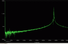
Here one can see the output spectrum when driven with a sinusoid at 20 dB below max input voltage.
The residual of the carrier can be clearly seen (between 350 and 400 kHz). The 1 kHz line can also be seen, followed to the right by its 3rd order harmonic (which is more than 80 dB down).
THD is remarkably rising with in creasing input signal level however. But it looks as if this simple circuit behaves quite well.
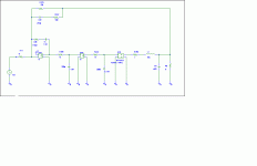
But it could be better and it lacks flexibility in terms of free choice of loop-gain oscillation frequency and overall gain. So I went further and developped a circuit that is a little more refined.
Attachments
The phase-shifter is now consisting of an integrator (= always 90 deg phaseshift) followed by a 2nd order lowpass. This lowpass has also 90 degrees phaseshift at its pole frequency. A 1st order allpass could also be used - which could be implemented veeeeeery cheaply - but I would be reluctant to do so in practice. I simulated with a Q of 0.5 and 1 both "worked" fine but showed slightly different properties. The example shows two 1st order lowpasses decoupled with a buffer. A Sallen-Key topology would also work. Even a fully passive lowpass would do. An even higher filter-order could be used but I don't see any advantage in doing so.
Also higher order integration could be used to further reduce THD. But they were detrimental to load independancy (which is very good with the single-loop topology) in my simulations.
In order to incorporate the output filter a PID is used instead of a simple integrator.
At an output amplitude of 10 % below maximum the switching frequency comes down to 0.5 times the idle freuency approx. This looks a little much but is still less than some hysteresis controllers and definitely better than the Tripath amps whose switching frequency varies by several octaves. The frequency variation can be minimised with an easy and cheap trick. This also improves THD at high levels at the cost of low level THD performance.
I will post some simulation results later on.
Have fun !
Charles
Attachments
Hi Timo
No it isn't but the topology in question is discussed also (fig 15) and the authors are the same ones.
Regards
Charles
No it isn't but the topology in question is discussed also (fig 15) and the authors are the same ones.
Regards
Charles
Thanks alot Charles appreciate the effort.
In the past I've tried modulating the hysteresis bands to achieve fixed frequency, not sure which would be easiest, maybe even a combination of the two. Yet as you point out it is extremely difficult to beat the simplicity of UCD. It's a pity for those who have to. Then again a fixed delay in UCD is not unheard of either.
Regards,
Chris
It's a pity for those who have to.
No it is a CHALLENGE* !!! 😉
Regards
Charles
* P.S. Maybe I am already brainwashed by all the manager babble one has to bare all day long !!
I'm up for the challenge right here right now. Does anybody know a clever way of mesuring carrier frequency vs. modulation index or duty cycle in pspice (Orcad's version). I can't find any build in macros or functions that let's me do any mesurements in the fourier domain. All of them works in time domain.
Charles I've attached a little simplification to your schematic, which btw works very well. I'm working on adding more feedback to it, so far I've achived ~20dB better supression of disturbances @10kHz.
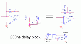
I think you should add a delay to your design, right from the start. You probably know how to do this, but for all you other guys it's shown in the attachment.
Attachments
This simplification would indeed make sense for a production unit ! For fiddling around with prototypes seperate filters might be more convenient.
Regards
Charles
Regards
Charles
I still owe you the answer how the frequency drift can be minimised. The two phase-shifting LPFs can be made LAG filters by using small resistors (1/10 to 1/4 of the other R) in series of both capacitors. The idle frequency will go up by doing this but that can be compensated for by the use of larger caps.
Regards
Charles
Regards
Charles
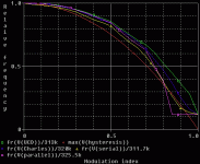
Okey, I've done a simulation on relative carrier frequency vs. modulation index for some different configurations (basic UCD, Charels design, Charles with added serial feedback, Charles with added parralel feedback and ideal hysteresis modulator).
The selfoscillationg designs beats the ideal hysteresis modulator, but it's not astonishing. It can also be seen that the more feedback there is the faster the frequency drops. This is an effect of carrier feedback.
The selfoscillationg designs beats the ideal hysteresis modulator, but it's not astonishing. It can also be seen that the more feedback there is the faster the frequency drops. This is an effect of carrier feedback.
Attachments
Attachment for the post above.
Included is a .gif schematic and Orcad files (v10.3).
BTW. I know Michael A. E. Andersen the co author of "Hysteresis Controller with Constant Switching Frequency". Maby I can get some readable schematic values and include it in the comparison.
Included is a .gif schematic and Orcad files (v10.3).
BTW. I know Michael A. E. Andersen the co author of "Hysteresis Controller with Constant Switching Frequency". Maby I can get some readable schematic values and include it in the comparison.
Attachments
Originally posted by analogspiceman [the start of this thread ...remember?]
There is a recent paper out of the Technical University of Denmark by Poulsen and Andersen that compares the class-d audio performance of various types of self-oscillating power convertor topologies: Self Oscillating PWM Modulators, a Topological Comparision
They claim that the phase shift sinewave feedback of the UcD type modulator circuit is measurably worse than the sawtooth feedback of an optimized hysteresis design.
This, they claim, is because the straight lines of a sawtooth lead to more linear large signal modulation and transient behavior when compared to the curvy lines of the UcD type modulator (especially when operating at high levels near the peaks of the sine wave feedback signal).
They call their intentionally linearized hysteresis circuit, AIM (astable integrating modulator), and call the phase-shift, self-oscillation modulation scheme utilized by the UcD family, COM (controlled oscillation modulator). Their implementation of their AIM circuit also largely eliminates the problematically large frequency excursions suffered by standard hysteresis modulators.
Like many such papers, this one and the others in this series, aren't especially good at clarifying design details or explaining how it all really works (probably this is intentional). They include some schematics, but they are reduced in size to the point that the component values are illegible. After a just a few readings, I have only a tentative opinion as to what they are up to (and reserve the right to completely reverse myself 🙂), but it seems that there are two pillars upon which rests the foundation of their design.
First, they take into account the contributions at the switching frequency of all of the feedback paths to the modulator, including any little bits of carrier that get through via global feedback. These are all summed and shaped over frequency to achieve a first order ideal integrator at the modulator input, which is what is necessary to produce the ideal linear sawtooth from the rectangular output stage switching waveform.
Second (and this is the novel part I'm less sure of), they cascade two hysteretic comparators in series, the first of which is the usual one, and the second of which seems to provide a more-or-less fixed time delay that generates a significant portion of the phase shift that determines the frequency of self oscillation (although they don't describe it in these terms).
As to the answer to the question of the subject line, I haven't made up my mind, yet. Time permitting, I intend to draw up and post simulation schematics of this idea to compare against the UcD and others.
[... and much later in the thread]
I still had to guess at several pieces to the puzzle, though. The inductor sense winding was not specified, the comparator and output stage voltage saturation voltages were missing as were their delay times. Oh, and the load.
The following values yield a fair match to the waveforms of your paper: an 8 ohm load, a 20 to 1 current transformer turns ratio (inverting), +/- 7 and 40 volts for the saturation levels, and 10 and 300 ns for the comparator and output stage delays, respectively. (Without a realistic output stage delay the circuit doesn't seem to work at all.)
How'd I do, guess-wise? 🙂 (Please feel free to jump right in and correct me.)
Here's the LTspice simulation schematic ... and here's the LTspice simulation file.
Not only was Jaka Racman kind enough to update me with the previously unreadable information (he had a copy with better detail than the one I got from the IEEE), but he directed me to a source of the remaining missing information. Thanks again Jaka.
About the guesses, the load was 8 ohms, the current transformer feedback ratio was indeed -0.05 and the output saturation level was +/-40 volts, but the delay comparator saturated at +/-7.5 volts and the IC delays were 100 ns and 218 ns for the comparator and output stages, respectively. With these values in hand, it should now be possible to set up an equivalent simulated UcD style class-d design (same quiescent switching frequency, etc.) and attempt to compare distortion figures. Please make these changes to the LTspice file linked above.
Originally posted by Sander Sassen
How about a load invariant frequency response? I find that to be one of the winning features of the UcD concept. Does the AIM concept provide this too?
The AIM design referenced above most certainly does not seem to, although this may not be because of its "AIM" aspects. Perhaps after distilling the essence of AIM, it will be clear that it will lend itself to load invariant forms as well (or not).
Regards -- analogspiceman
Hi,
I'm very much looking forward to your results analogspiceman.
Looking forward to your results with great interest, and thank you for sharing this all this in public domain, same to you Charles and Sovadk.
Sovadk I'd also be interested in seeing your working equation which produced those graphsl.
Regards,
Chris
I have no equations, except for the ideal hysteresys modulator. The graphs are made from simulation of the attached orcad schematic.
I've modified the "period()" goal function in PSpice to mesure the frequency after a 40us settle time over 15 periods. The x axis is the dc input voltage to the amplifiers. After calibration the dc_in corresponds to the modulation index.
I've quoted the code for modified period() goal function here:
I would have preferred an analysis in the fourier domain, but PSpice has no features for this. Generally the features for signal analysis are lagging. I wonder why this software is so expensive.
I would like to exploit the auto optimization features of the Orcad suite, but without proper goal functions it seams impossible to me.
I wrote a goal function to detect the frequency where the phase crosses -180 degrees, in order to predict the closed loop oscillation frequnecy. It worked fine, as long as the phase did cross -180 degrees. When it didn't the optimization feature halted. Why! It should just continue with some new random component values.
Does anybody have experience and solutions for this?
I've modified the "period()" goal function in PSpice to mesure the frequency after a 40us settle time over 15 periods. The x axis is the dc input voltage to the amplifiers. After calibration the dc_in corresponds to the modulation index.
I've quoted the code for modified period() goal function here:
fr(1) = 15/(x2-x1) { 1|Search forward (40u,200u) level (50%, p) !1 Search forward (40u,200u) 15:level (50%, p) !2; }
I would have preferred an analysis in the fourier domain, but PSpice has no features for this. Generally the features for signal analysis are lagging. I wonder why this software is so expensive.
I would like to exploit the auto optimization features of the Orcad suite, but without proper goal functions it seams impossible to me.
I wrote a goal function to detect the frequency where the phase crosses -180 degrees, in order to predict the closed loop oscillation frequnecy. It worked fine, as long as the phase did cross -180 degrees. When it didn't the optimization feature halted. Why! It should just continue with some new random component values.
Does anybody have experience and solutions for this?
sovadk said:Okey, I've done a simulation on relative carrier frequency vs. modulation index for some different configurations (basic UcD, Charles' design, Charles' with added serial feedback, Charles' with added parallel feedback and ideal hysteresis modulator).
The self-oscillating design beats the ideal hysteresis modulator, but it's not astonishing. It can also be seen that the more feedback there is the faster the frequency drops. This is an effect of carrier feedback.
I've always looked at the frequency down-shift as a result of the extra 90 degrees of phase shift (input to output of the power stage) that comes from the asymmetrical switching waveform when operating near the rails. The fundamental Fourier component of the zero-output squarewave has no excess phase shift, so the operating frequency has to be at its highest in order to get the required phase shift around the loop from the delays and linear feedback elements alone.
By the way, there are schemes to stabilize the frequency of hysteresis based amplifiers. These take the voltages around the switching stage and the derivative of the inductor current command as inputs, do some reasonably straightforward math (unfortunately requiring multiplication and division) and come up with dynamically varying hysteresis thresholds. I've made up an LTspice simulation (signal math is easy) that seems to stabilize operating frequency rather well. I'm hoping to get the time to wrap the rest of an amplifier around it and see if it: 1) actually seems to work; and, 2) has any less distortion near the rails than does UcD.
The AIM circuit that started this thread seems to have disappointing load dependence. Perhaps the original author would care to comment.
 By the way, sovadk, have you checked the AIM configuration (claims to offer better frequency stability) against the others in your simulation test?
Regards -- analogspiceman
Hi Lars,
So you're saying you're a believer in load dependant frequency response?
We can disagree.
Regards,
Chris
So you're saying you're a believer in load dependant frequency response?
We can disagree.
Regards,
Chris
Looks like Lars, how do you say, redacted his post. It's still available via my back button, however. 😀
Originally posted by analogspiceman
By the way, there are schemes to stabilize the frequency of hysteresis based amplifiers. These take the voltages around the switching stage and the derivative of the inductor current command as inputs, do some reasonably straightforward math (unfortunately requiring multiplication and division) and come up with dynamically varying hysteresis thresholds. I've made up an LTspice simulation (signal math is easy) that seems to stabilize operating frequency rather well.
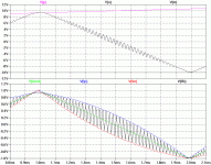
Okay, an LTspice simulation output plot demonstrating this control scheme should now be attached. 🙂
In the top window are the rail voltages (positive rail is ramping slightly) and the output voltage (note that voltage is not the controlled quantity - current is). The bottom window shows the current through the output inductor (Ifb), the current command and the dynamically varying plus and minus hysteresis limits. Frequency gets a little weird right around the rails but is otherwise fairly constant.
It is important to note that there is no voltage feedback. As the AIM guys point out, when this outer loop is closed, the switching ripple that shows up in the current command may completely distort or disrupt the expected operation of the current loop. Perhaps AIM style feedback would cure this, or perhaps it will not be a problem with leapfrog style feedback (or a combo of these). Hope I find the time to work on it this weekend.
The positive delta hysteresis limit equation: V=.5*(V(p,o)/V(p,m))*(V(o,m)/{f*L}+I(Vdi)) ; p & m are rails, o is output
And the negative: V=.5*V(o,m)/V(p,m)*(V(p,o)/{f*L}-I(Vdi)) ; p & m are rails, o is output
Regards -- analogspiceman
Attachments
serengetiplains said:Looks like Lars, how do you say, redacted his post. It's still available via my back button, however. 😀
It was probably a very good idea. We've been down that road before and it got ugly. Good thing I didn't quote it.
- Status
- Not open for further replies.
- Home
- Amplifiers
- Class D
- Is the UcD modulation scheme less than optimum?
