Thank you Osvaldo to point that,
In fact I have a current limited supply, a Light bulb tester (basically a 300w filament bulb in serie with the mains live)
Hi, this my limited power supply. The three lamps are independently switchable with the 3 black switches at the bottom left corner (from the 1970's), it may be paralleled to give 100, 200, 300, 400 500 and 600W in series. The outlets are below the work bench. Note here the supply is 220VAC (Under normal conditions).

The input Power to an amplifier is expressed in Watts. But the VA (Volt Amps) of an amplifier
is more than the Watts. This is due to the different phase of the Volts and the Amps at the transformer primary (and phase of the loads on the secondaries). The inductances and capacitances cause this phase shift. This effect is called PF (Power Factor).
If you take the Cosine of the phase (0 degrees to 90 degrees) you get the PF.
For example, an amplifier with a phase of 36.9 degrees will have a PF of 0.8
Watts / PF = VA.
An amplifier that is rated at 100 Watt power draw, and a Power Factor of 0.8 will have 125 VA.
125VA / 230V = 0.54 Amps.
If the phase is 53 degrees, the PF is 0.6. 100W / 0.6 = 167VA 167VA / 230v = 0.73 Amps.
Another factor is the large inrush current at turn-on, and soon after turn-on.
It can be several times the steady state current. It depends on the power supply,
cold filaments, warm up of rectifiers, output tubes, input tubes (especially with RC or DC coupling from that stage to the output stage), regulators, etc.
The inrush current is also dependent on the exact moment you turn on the amplifier.
Turn it on at the power line sine wave zero crossing, you get less inrush.
Turn it on at the power line sine wave peak, you get much more inrush.
AS ALWAYS, WORKING ON ANY PRODUCT THAT IS POWERED OFF THE POWER MAINS,
YOU MUST BE KNOWLEDGEABLE, AND TAKE CAUTION. THE MAINS, AND THE PRODUCT CIRCUITS CAN KILL.
So, what are we to do?
First of all, we must have the amplifier working properly, and without any failure of any circuit.
Then you can use a smaller fuse and see if it does not fail.
If it fails at first turn on, it is too small. But don’t stop there if it does not fail at first. Let the amp warm up, and see if it still works. Then power it down and let it cool. Later when it is cool, turn it on again (we are trying to turn it on cold, and when the power sine wave peaks). How many times do you have to do this … it is by chance.
If it does fail, use the next larger amperage fuse. And test again.
Sometimes, a Hot start will cause the fuse to blow. This happens when the amp is warm
and a power line goes out briefly, say 1/2 second. The lights flash off/on. But the amp
is warm, and the fuse blows.
Sometimes a fuse just fatigues. This happens when the Amp draw is almost equal to the fuse Amp rating, or many many turn-ons at the power line (Mains) sine wave peak. I have had fuses fatigue after 1 or 2 months. Then the new fuse may not blow again, even after several months (fuse ratings have a tolerance, they are not perfect or exact).
IN NO CASE SHOULD YOU USE A FUSE WITH A LARGER AMP RATING THAN WHAT THE MANUFACTURER SPECIFIES.
PAY ATTENTION TO THE TYPE OF FUSE, YOU MUST USE THAT TYPE (FAST BLOW FOR FAST BLOW; SLOW BLOW FOR SLOW BLOW).
I believe you are making your power supply more friendly to the rectifier, the high voltage secondary, and are not going to bias more current in the output stages than in the original design. So, I expect the amp to draw less Watts and VA (with less capacitance immediately after the rectifier and before the choke), and to have as good or better PF.
I do not subscribe to using fuses in the high voltage secondary (suppose one fuse fatigues
or correctly blows; but now the other rectifier plate and 1/2 secondary are struggling).
Putting it in the high voltage secondary center tap is not a good idea either. Number 1, Safety … you still can get surprised and nailed; and what protection is there if the rectifier plates short, or the wiring shorts.
I also do not recommend using MOVs in the amplifier.
Using a MOV from the rectifier plate to the B+ will destroy the filter capacitor if there is a transient that activates the MOV. (Protect the rectifier, blow the capacitor, and maybe the high voltage secondary too).
If you have power line problems, transients, etc., then you should be using a transient protection rated multi output power strip. (guess what, they use MOVs). Put the protection in the hands of the professionals (hopefully) that designed and built the transient protection power strip.
I take old amplifiers and use the power transformers. I design a completely different circuit.
But I always am careful to use less power from the transformer secondaries than was in the original amplifier. So sometimes I can use a fuse of Lesser Amp rating than the original.
If the manufacturer specifies a fast blow fuse, I use a fast blow.
If the manufacturer specifies a slow blow fuse, I use a slow blow.
I even double protect by double fusing (series fuses, one fast blow, one slow blow).
THIS IS FOR VERY KNOWLEDGEABLE AND EXPERIENCED AMP DESIGNERS.
I use solid state diodes in the B+. When possible, I use the more friendly choke input B+, since there is no rectifier resistance in series to the first filter cap, just the DC resistance of the choke.
And sometimes I use solid state diodes to get DC filaments.
Rectifying and CRC filters draw 1.8 times the filament current (1 Amp filament requires 1.8 Amps from the filament secondary).
For the primary fuse:
Suppose I am using the original 1.25 Amp fast blow fuse, and suppose that works fine, and a lower 1 amp fast blow fuse does not (I can not use a fuse of lower rating).
But suppose that amp only draws 0.5 Amp after it warms up. I find that I can also wire a 0.6 Amp slow blow fuse in series with the original 1.25 Amp fast blow fuse.
If the 0.6 Amp does not blow, I am double protected:
Now if the inrush exceeds 1.25 Amp the 1.25 Amp fast blow fuse blows open.
Now, if the warmed up amp has a failure that causes a draw that exceeds 0.6 Amp, but does not exceed 1.25 Amp, the 0.6 Amp slow blow fuse blows open. Double protection.
I think I will go with two fuses in serie (one fast as in original schematic and one slow) I'll need to find the good value for each of them.
Here the "maybe" final schematic for my modified PSU:
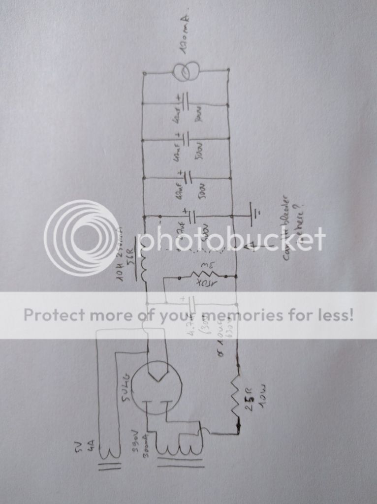
May I leave the bleeder on the first cap after the choke?
Cowneko, What is that number you are writing that looks live an upside-down V on your choke, the output load, and the resistor wattage? No numbers I've ever seen...
Cowneko, What is that number you are writing that looks live an upside-down V on your choke, the output load, and the resistor wattage? No numbers I've ever seen...
That's 10H
The resistors are:
25R 10W
150K 3W
The load is 170mA
That's 10H
The resistors are:
25R 10W
150K 3W
The load is 170mA
Well, your 7 looks like a 2 and the 1 looks like a wonky overly flecked , drunken 7.
I wish I was drunk, but sadly I only got flu...so writing between two coughs.....you know....😀
Not you drunk, just the 7 that's a 1, or the 1 that's a 7, but not the 2 that's a 7, or the 7 that's a 2. Just the 1 that's a 7 bending over. It looks like it's bending over getting ready to puke.😱

Last edited:
 Shh!! don't tell anyone
 So I made the modifications and done a series of measurements.
Here's an updated schematic (I tried ExpressSCH for a change 😉 ) I put the measurement results on the schematic:
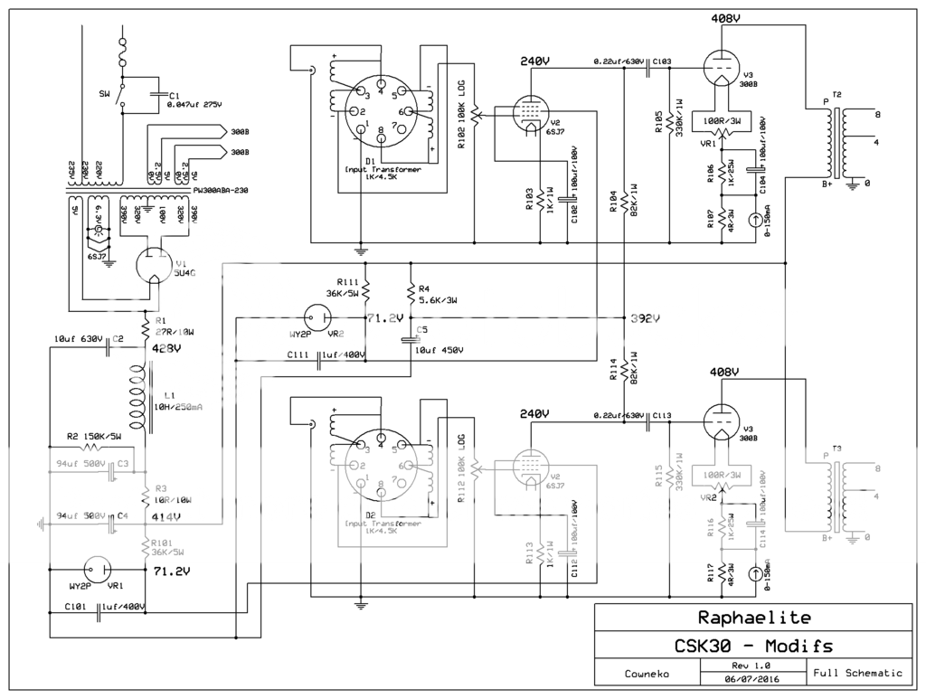
I had a problem with one of my WY2P regulators witch gave 75+ VDC when the other gave only 71.2VDC, I found another WY2P in my tube drawer witch gives 71.2VDC too so I replaced the strong one.
The Ammeters shows 60-61mA on each 300B
Here's an updated schematic (I tried ExpressSCH for a change 😉 ) I put the measurement results on the schematic:
I had a problem with one of my WY2P regulators witch gave 75+ VDC when the other gave only 71.2VDC, I found another WY2P in my tube drawer witch gives 71.2VDC too so I replaced the strong one.
The Ammeters shows 60-61mA on each 300B
From your revised schematic, I see the following factors:
Including the bleeder, 2 regulators, 2 300Bs and 2 6SJ7s, There is about 143 mA draw on the 5U4G, given the revised voltages you measured.
The HV Secondary 77 Ohms/2 = 38.5 Ohms plate to center tap.
38.5 + 27 = 65.5 Ohms.
The 5U4G sees 65.5 Ohms.
The minimum specified impedance driving the plate is 75 Ohms.
Any capacitance 40uF or greater may require more than 75 Ohms
(10uF requires 75 Ohms).
The 5U4G sees 65.5 Ohms, plus the factor of the DCR of the primary.
220V to 390V is a transformation upward of 1.77. 75 - 65.5 Ohms = 9.5 Ohms
9.5/1.77 = 5.4 Ohms. If your primary DCR is 5.4 Ohms or more, you are OK here.
The regulators have 7.7 mA. I do not have a regulator data sheet to see if that is enough current. If not, the 36k will have to be replaced by a slightly lower resistance.
The 6SJ7 plate is at 240V and 1.85 mA.
Before, the 6SJ7 was at 280V and 1.6 mA on the earlier schematic.
for a pentode, the plate current should either go down slightly, or
remain the same when the plate voltage goes down slightly.
But there could easily be that much from one tube to another.
The 300Bs see 408V - 61V bias = 347V
347V x 61 mA = 21.2W That should give them a longer life than the earlier higher voltage and higher current.
The damping factor probably has gone down just a little from before.
Likewise, the power before clipping has gone just down a little from before.
I think everything is OK and good.
The best thing to do now is use a good piece of test gear (your ears).
Just listen, and enjoy the music.
The HV Secondary 77 Ohms/2 = 38.5 Ohms plate to center tap.
38.5 + 27 = 65.5 Ohms.
The 5U4G sees 65.5 Ohms.
The minimum specified impedance driving the plate is 75 Ohms.
Any capacitance 40uF or greater may require more than 75 Ohms
(10uF requires 75 Ohms).
The 5U4G sees 65.5 Ohms, plus the factor of the DCR of the primary.
220V to 390V is a transformation upward of 1.77. 75 - 65.5 Ohms = 9.5 Ohms
9.5/1.77 = 5.4 Ohms. If your primary DCR is 5.4 Ohms or more, you are OK here.
Shall I just check the resistance across the primary winding? (230-0)
The regulators have 7.7 mA. I do not have a regulator data sheet to see if that is enough current. If not, the 36k will have to be replaced by a slightly lower resistance.
How do you calculate the regulator current draw (7.7mA)?
Minimum current for WY2P is 5mA and max 40mA (thanks to my wife that can translate Chinese 😉 )
So I'm good here 😉
How do you calculate the 1.6mA?The 6SJ7 plate is at 240V and 1.85 mA.
Before, the 6SJ7 was at 280V and 1.6 mA on the earlier schematic.
for a pentode, the plate current should either go down slightly, or
remain the same when the plate voltage goes down slightly.
But there could easily be that much from one tube to another.
How do you decipher the Bias voltage (61V) is it proportional to the Bias current (61mA)?The 300Bs see 408V - 61V bias = 347V
347V x 61 mA = 21.2W That should give them a longer life than the earlier higher voltage and higher current.
The damping factor probably has gone down just a little from before.
Likewise, the power before clipping has gone just down a little from before.
In the mean time I tested lower value for the mains fuse, I'm now on a 2.5A fast fuse and all is good (the original value of 5A seems way oversized), maybe I can go lower, but I don't have lower values on fast type.
I'll have to try the temporized type now.
And sure I'm listening to music (that's the point isn't it ? 😉 but I really enjoy learning in the process and it gives me the opportunity to have a more tube friendly amp.
Last edited:
Cowneco,
For your latest questions, here are the answers:
Minimum impedance for the 5U4G
You are probably OK with only 65.5 Ohms for the 5U4G. It is specified for 75 Ohms
and 40 uF, but you are using only 10 uF. It certainly is much better than the 47 uF you started with.
Yes, you can check the 230V primary if you want to be sure you have a total impedance of 75 Ohms. 390V/230V = 1.7. You need 9.5/1.7 = 5.6 Ohms DC Resistance in the primary wire.
If it is about 3 ohms or more, I would not worry about it. There is probably another 1/2 ohm in the fuse. 1/2 Ohm x 1.7 = 0.85 Ohm (everything counts).
6SJ7 plate current
Now: The plate is at 240V, the 82k Ohm resistor is at 392V
392V - 240V = 152V across 82k Ohm. 152V/82k Ohm = 1.85 mA
Earlier: The 6SJ7 plate is at 280V, the 82k Ohm resistor is at 410V
410V - 280V = 130V across 82k Ohm. 130V/82k Ohm = 1.58 mA (1.6 mA).
Regulator tubes
The regulators are at 71V. The 36k Ohm resistor is at 414V.
414V - 71V = 343V across 36k Ohm. 343V/36k Ohm = 9.5 mA.
9.5 mA - 1.85 mA (6SJ7) = 7.7 mA.
300B
You said the 300B current is 61 mA. I do not know how you measured it,
but I assumed it to be true. (by the way, the earlier version of your amp was 70 mA).
The filament self bias resistor is 1000 Ohms, plus the
4 Ohm meter shunt resistor = 1004 Ohms.
The calculation is 1004 Ohms x 0.061Amp = 61.2 V bias.
Fuse
What do you mean Temporized type fuse?
Do you mean a slow blow fuse ?
You can not change from a fast blow of one value, and change it to a slow blow of another
value. You will not get the same protection.
See my posts and thread on this site: “6A3 Cool Amp”.
For that amplifier power supply I used a 600mA slow blow fuse, and a 3 Amp fast blow fuse.
It is listed in the schematic. Every unique amplifier design would require a different combination of fuses.
300B
You said the 300B current is 61 mA. I do not know how you measured it,
but I assumed it to be true. (by the way, the earlier version of your amp was 70 mA).
The filament self bias resistor is 1000 Ohms, plus the
4 Ohm meter shunt resistor = 1004 Ohms.
The calculation is 1004 Ohms x 0.061Amp = 61.2 V bias.
I took the 61mA from the Ammeters, maybe it's not the most precise way to do it... (If you can tell me a more reliable way to do it, I'd be really grateful)
Fuse
What do you mean Temporized type fuse?
Do you mean a slow blow fuse ?
You can not change from a fast blow of one value, and change it to a slow blow of another
value. You will not get the same protection.
See my posts and thread on this site: “6A3 Cool Amp”.
For that amplifier power supply I used a 600mA slow blow fuse, and a 3 Amp fast blow fuse.
It is listed in the schematic. Every unique amplifier design would require a different combination of fuses.
Of course I'll keep the fast one, but I have to find out the right value for the slow blow witch will be put in serie with the fast one.
All in all, thanks a lot for all your explanations 😉
Cowneco,
The 300B bias resistance is ~ 50 Ohms (hum pot), plus 1000 Ohms, plus 4 Ohms (meter resistor).
With the amp off, and all the capacitors discharged, measure the resistance from either pin1 or pin4 (filament) of the 300B to ground. Wait until the meter has charged the bypass cap, and
the reading has settled. Note this resistance.
Then, switch the meter to DCV (You can destroy a meter that is set to Resistance, and then putting voltage across the meter leads).
Now, measure the DCV from either pin1 or pin4 of the 300B to ground. Note this voltage.
Voltage/Resistance = Current.
For example, 62VDC/1054 Ohms = 0.0588 A = 58.8 mA.
Hi,
The amp sound great, but seems like the 10uf poly cap tend to stiffen the sound (a little more harsh) so I tried substituting it for a 22uf Elco cap (measured 24uf) and put a .22uf poly bypassing the last 94uf cap; It's far more relaxed this way. I think rectifier shall be able to cope with 24uf first cap just fine.
However, I measured the primary and secondary resistance of the power transformer to find the right amount of additional res to add.
Here the measurements:
-(Rpri) Primary DCR= 4R65
-(Rsec) HT Secondary DCR (across the whole secondary)= 78R40
-HT secondary to center tap A= 38R20
-HT secondary to center tap B= 40R20
-->I will assume 39R2 half secondary resistance
- (Vsec) Unloaded HT secondary voltage (each plate)= 403V
- (Vpri) Mains voltage= 230V
So for the calculations;
The Raa (without additional resistance):
Raa = Rsec + Rpri × (Vsec/Vpri)²
Raa= 39,2+4,65 x (403/230)²
Raa= 53R48
For a 5U4G/5Z3 tube, at 403V (unloaded plate voltage) the tube needs more or less 71R of total DC resistance per plate from the transformer. So I need 17R resistor between cathode and first cap.
Am I right?
Cowneco,
I am sorry I did not respond quickly to your latest question.
Some 5U4G/5Z3 specifications call for 75 Ohms at each plate. Some also call out a maximum
32 uF first filter cap.
According to my calculations you need to use at least 23 Ohms, not 17 Ohms. You should use a 25 Ohm resistor. You need to use a True rms DMM to measure the voltage across the 25 Ohm resistor, then calculate current, I, through the resistor. I = Vrms/25 Ohm. Of course you have to use good high voltage probes, keep your hands out of the circuit, and take all safety
precautions.
Then use this formula to determine the power in the resistor: (I) squared x R. Use a 25 Ohm resistor with a power rating 5x this calculated power.
You will almost certainly not hear the difference between a 25 Ohm resistor and a 17 Ohm resistor. But you will be within the specifications of the 5U4G/5Z3 rectifier.
Some rectifiers may not hold up reliably when used at or near their maximum ratings, and even the good ones will last longer when used more conservatively, and run cooler too. Now some of
that heat will be in the 25 Ohm resistor instead of in the rectifier.
That should finish your modifications of your circuit.
Now have fun listening.
- Status
- Not open for further replies.
- Home
- Amplifiers
- Tubes / Valves
- Is my 274b/n defective