The resistor placed in the negative wire is directly in series with the other in the rectifier's cathode, so, no mean the this resistor be there.
Why not to try, as I mentioned above, removing the first cap and the resistor, and wire the inductor directly to the cathode? This will convert into the choke input filter that is less rectifier abusive.
Why not to try, as I mentioned above, removing the first cap and the resistor, and wire the inductor directly to the cathode? This will convert into the choke input filter that is less rectifier abusive.
The resistor placed in the negative wire is directly in series with the other in the rectifier's cathode, so, no mean the this resistor be there.
Do you talk about the 47R resistor or the two 100r of the virtual center tap?
Why not to try, as I mentioned above, removing the first cap and the resistor, and wire the inductor directly to the cathode? This will convert into the choke input filter that is less rectifier abusive.
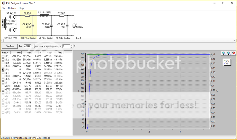
I tried this configuration in PSUdesigner
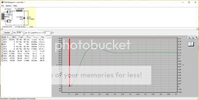
It lowers B+ by 140V, quite much don't you think?
It also induce a ripple of 1V peak to peak, wouldn't it be a problem to?
Any resistor between the CT and ground is equivalent to one placed between the cathode of the rectifier and the first cap. And if you place both, they are added directly.Do you talk about the 47R resistor or the two 100r of the virtual center tap?
I tried this configuration in PSUdesigner
It lowers B+ by 140V, quite much don't you think?
It also induce a ripple of 1V peak to peak, wouldn't it be a problem to?
It depends on the application. I don't know about this software, bit if you can see the input current to the transformer, you will see the difference. And this difference is also in the tube current.
Independently of the choke value, and supposing the choke doesn't saturate (Air gap is more or less correct for the Ac voltage and DC current flowing in the wire), the output voltage will be about 90% of the AC RMS secondary voltage with choke input filter, minus the rectifier and the DCR loss in the choke. It also supposes that the choke doesn't run dry, say, that current permanently flows in it, which in turn, means the the minimum output current doesn't go below the critical current, or the load resistance in ohms is about 1000 * L in henry.
For more details see Choke or Capacitor Input?
For more details see Choke or Capacitor Input?
Last edited:
Independently of the choke value, and supposing the choke doesn't saturate (Air gap is more or less correct for the Ac voltage and DC current flowing in the wire), the output voltage will be about 90% of the AC RMS secondary voltage with choke input filter, minus the rectifier and the DCR loss in the choke. It also supposes that the choke doesn't run dry, say, that current permanently flows in it, which in turn, means the the minimum output current doesn't go below the critical current, or the load resistance in ohms is about 1000 * L in henry.
For more details see Choke or Capacitor Input?
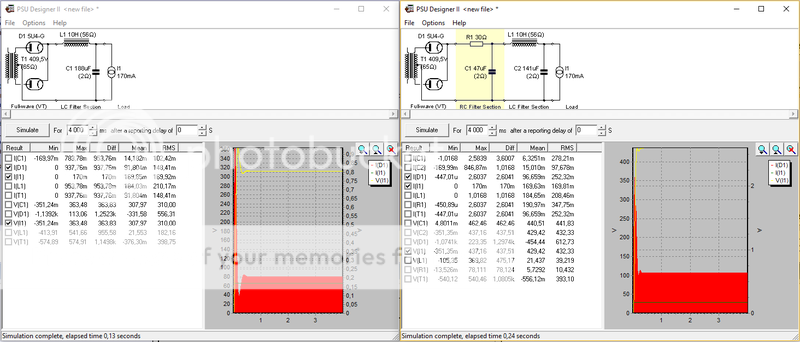
You're right, the inrush current on the rectifier is lowered by a large margin with a choke input filter, witch should be a lot more friendly for the tube.
here a comparison between original and choke input filter (red=inrush current on the rectifier, green= current on the load, yellow= voltage on the load)
A caress to my ego.
if this soft has a simulated oscilloscope, simulate input current to the transformer in both circumstances. Note te difference between them.
Capacitor input to the filter has that input current is very peaked, lots of 3rd harmonic.
Inductor input has a much more sinusoidal current.
This is the main advantage.
Last edited:
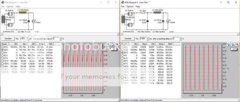
Zoom in on the rectifier current curve (it's the same when took from the transformer)
Seems like the choke version is less sinus with spikes.
Seems like the choke version is less sinus with spikes.
Maybe I am missing something but the choke input appears to show much less current which is as you would expect compared to the cap input. Hard to tell though because the attached pictures are tiny.
Try removing the resistor between rectifier's cathode and the firts cap. Observe how worse are the current peaks...
Take a reading at this:
http://www.ax84.com/static/rdh4/chapte30.pdf
Enjoy.
Take a reading at this:
http://www.ax84.com/static/rdh4/chapte30.pdf
Enjoy.
Plate current 65 ma, IMHO, is not very good mode for good sound. I had SE 300B and I used mode 85-90 ma with sound more better than 65-70 ma.
Another person asked you about the better sounding amp at 85-90 ma (better sound than the 65-70 ma amp), what was the voltage [across the filament to plate]?
So what was that voltage?
I ask what was the output transformer primary impedance?
And were the voltages and primary impedances the same, or different, for the 65-70 ma and 85-90 ma amplifiers?
OK,
I tried the tube with a bench DC PSU, One of the filament is dead, it doesn't lit and the tube draws only 1.66A at 5V. The tube is busted.
you're right about the input filter, the first component after the rectifier+res(// to regulators) is the first 47uf cap of the double 47uf 500V cap then the choke.
Shall it be possible to:
1. putting a 2.2 or 3.3uf 600v PP cap first, then the choke, then the two double 47uf caps?
2. converting the capacitor input filter to a choke input filter (choke, then first double 47uf cap, then resistor, then second 47uf cap)?
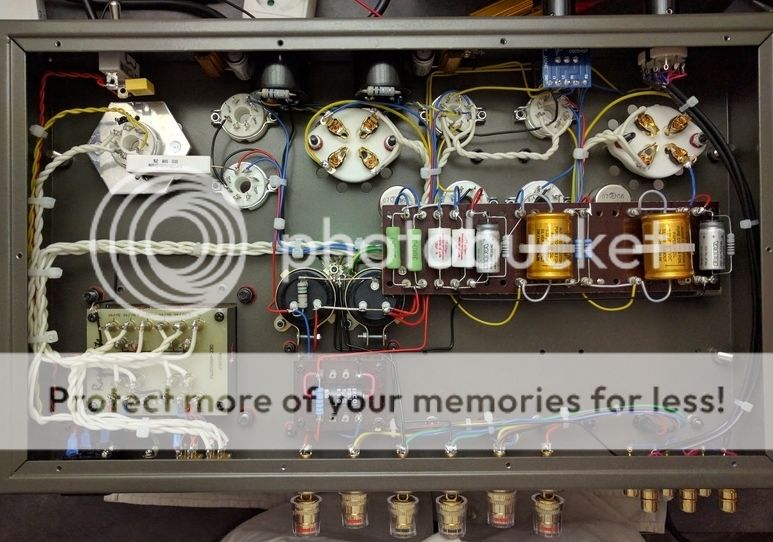
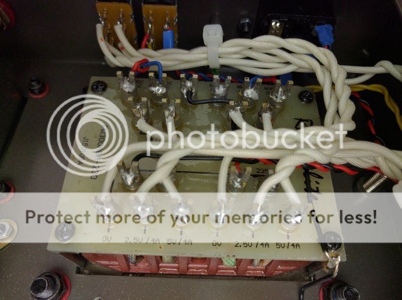
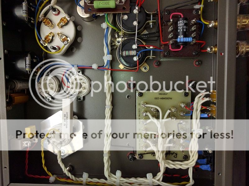
here some picture of the amp innards:
Making just one single change to an amplifier design can require many other changes to the circuitry in order to have it all work well together.
Using a 2.2 uF, 3.3uF or even a 4 uF first capacitor will certainly make the rectifiers job easier (I often use 4uF, because it lightens the rectifier load, but retains some of the higher B+ volatage). Some of the rectifier’s data sheets specify rather large maximum capacitance for capacitor input filters. But many of those same data sheet graphs and suggested operating values use only 4 or 10 uF capacitors (it is kind of a marketing thing, I think). Those maximum capacitance values of 20uF, 33uF, or 40uF are only for lower plate voltages, lower load currents, or both.
You can try using the smaller input capacitor, but you will have much lower B+ Voltage. The problem is not just getting the 300B circuit re-adjusted, but also the driver tube circuits, and the regulator tubes circuits.
It just might work OK using a 4uF input capacitor, and move the 47uf ‘downstream’ to the other one. If there is too much hum, you will need a resistor after the choke, so you will have 4uF, choke, 47uF, resistor (100 Ohms will drop about 17V), 47uF.
Your amp has 5k Ohm primaries on the output transformers. They need a certain voltage swing amount to get a specified output power. And that voltage swing requires a certain current amount, as well to have the damping factor remain the same. With the lower B+, the 300B quiescent current will drop, you will get less power, and a lower damping factor. You can get back part of all of those by using a lower self bias resistor (you now have 1k Ohm bias resistors in the 300B filament circuits). How much lower depends on the new B+ voltage.
Use bias resistors that will give about 60 to 70 mA current. Start with small changes, 900 Ohms, 820 Ohms, 750 Ohms and see if that gets the current back. These need to have 25 Watt ratings.
At 60 mA, you will get the following voltages across the resistors: 900 Ohms, 54V; 820 Ohms 49.2V, 750 Ohms 45V.
At 70 mA, you will get the following voltages across the resistors: 900 Ohms, 63V; 820 Ohms 57.4V, 750 Ohms 52.5V.
For example if the 820 Ohm resistor gives between 49.2 and 57.4 Volts, the current is between 60 and 70 mA.
Using a choke input filter on this amp will cause the B+ voltage to drop severely. And the choke may not be up to working as an input choke (as already mentioned by another person in this thread).
So, shall I go to something like this:
I have an obbligato 4.7uf 630v Pio waiting to be of use 😉, I'll move the 30r 10 w after the choke and put a 10R 10W as first res, does it seem good to you.
For the adjustement of the 300B cathode resistor, I plan to try some 2w resistors in parallel (9k, 4k7....) I think 2W is enough right?
I guess I'll have to tweak the resistor of the regulator too (the two 36K 5W), I may use the same method here, with some 2W res in // in order to still get 74V at the 6sj7 grid, right?
Is there anything else to consider?
In your case, and in any where there is a serious component doubt, I would do as follows, and as I always do in my job (Electronic repair) and at house:
Replace the load with any other which in case of destructive failure, don't worry (For example, remove all tubes in the amp and replace them with a combination series and parallel of filament lamps, for an equal power consumption as the tubes do). Then, energize the set from a current limited supply, for example, wire it in series with a kettle, or other resistive load with much high power capacity than the load.
Switch on the set, and wait to see if anything is OK. If the rectifier under doubt is failed, then it will destroy itself without damage to an expensive component or element, and if it definitively fails, the series device in the power line will limit the level of destruction, preserving the trafo and capacitors life. If it continues OK, then search the problem in another device in the amplifier.
Believe, I do it almost every days. If not, you always will live with the doubt.
The brand of a capacitor is secondary importance, the elementary is to see if it it will support the job.
Thank you Osvaldo to point that,
In fact I have a current limited supply, a Light bulb tester (basically a 300w filament bulb in serie with the mains live)
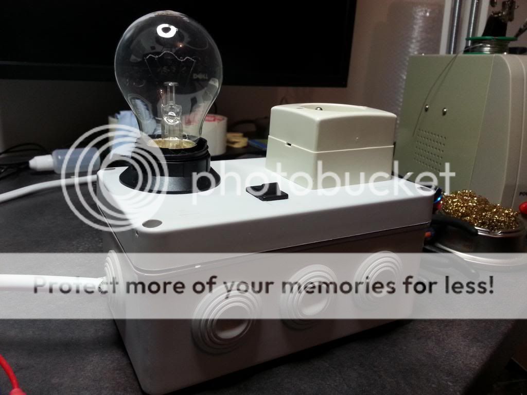
In fact I have a current limited supply, a Light bulb tester (basically a 300w filament bulb in serie with the mains live)
So, shall I go to something like this:
An externally hosted image should be here but it was not working when we last tested it.
I have an obbligato 4.7uf 630v Pio waiting to be of use 😉, I'll move the 30r 10 w after the choke and put a 10R 10W as first res, does it seem good to you.
For the adjustement of the 300B cathode resistor, I plan to try some 2w resistors in parallel (9k, 4k7....) I think 2W is enough right?
I guess I'll have to tweak the resistor of the regulator too (the two 36K 5W), I may use the same method here, with some 2W res in // in order to still get 74V at the 6sj7 grid, right?
Is there anything else to consider?
The transformer is 92 Ohms from plate to plate. You need about 72 Ohms to Each plate (5U4G Capacitor Input Data Sheet Curve for 410VAC (secondary to center tap). 92/2 = 46 Ohms. Any resistors in your circuit, center tap to ground, or filament to the 4.7 uF cap add up, you need about 26 Ohms. There is lots of current, and capacitor input rms current is about 1.8 times the DC load current. 1.8 times 0.170 Amp = 0.306 Amp.
I squared R = 0.306 times 26 = 2.43 Watts. A good rule for resistors is to keep the rated watts about 5 times higher than the dissipated watts. 2.43 w times 5 = 12 Watts. A 25 Ohm, 10 Watt resistor will do here, and still remain cool. You can either: 1. Put it from filament out to the 4.7 uF cap. Or, 2. You can put it from the secondary center tap to ground. The second option is a good way to allow you to safely see the current waveform across that resistor to ground.That current will surprise you at how large the Peak current is at each alternation. In any case, you only need a resistor in one of those places.
The resistors to the regulator tubes will probably Not have to be changed. There is about 8 mA in each one, and less than 1 mA to the driver tube screen. OK, just check that there is still about 74 Volts at the regulator (if it is lit, you will almost certainly find is in the range of 74 V).
300B Bias: If you use two 9,000 Ohm in parallel with the 1k Ohm, you get 818 Ohms. You will get less than 70V, maybe 60V. E squared / R = Watts. 60 squared / 9000 = 0.4 Watt, each resistor. Times 5 that is 2 W. use 2 W resistors here.
If the tube current is 60 mA, with 818 Ohms you will have 49 V bias.
If the tube current is 65 mA, with 818 Ohms you will have 53 V bias.
If the tube current is 70 mA, with 818 Ohms you will have 57.3 V bias.
If you use a 4,700 Ohm in parallel with the 1k Ohm, you get 825 Ohms.
60V squared / 4700 = 3/4 Watts. Use a 5 Watt resistor here.
You can see what to do to get the current you desire. But remember, as
the bias voltage goes down, the maximum output swing will also go down.
But less bias voltage and more current will have a higher damping factor over the output swing that you get.
You could also try using 2A3 tubes on the reduced B+ that you have when
the 390VAC is applied to the rectifier, and from the rectifier to the 4.7 uF cap.
But you will have to check what the B+ voltage is on the 300B tubes, to see
just how low the B+ is.
I do not know if the filament selector switch for 2A3 or 300B is a separate switch from the 2A3 or 300B B+ selector switch. If they are Not separate, you could wire the B+ permanently in the 390VAC position. If they are separate, then you would not have to do that. In either case, select the correct filament switch setting.
The 2A3 can be operated at 300V plate to filament, with 50V bias in a 1 k Ohm Resistor (60 mA, times 300V, which is 15Watts). That works with a 350V B+
The 2A3 can be operated at 250V plate to filament, with 43V bias in a 750 Ohm Resistor (60 mA, times 250 V, which is 15Watts). That works with a 290V B+.
With the reduced B+ volts that you have, you might be able to find a combination bias resistor that will work for both 300B and 2A3 at a fairly optimum operating point. Just a way to do tube tasting. It should even work with out changing the bias resistor value from 1 k Ohms.
With 1k Ohm, you have 1 mA / Volt of bias.
you might have less hum with 2A3s than 300Bs.
My latest amplifier can use a 6A3 or a 300B. It uses DC filaments and 2 Ohms between filament filter caps. A 0.47 Ohm resistor in series with the 2 Ohm resistor, with a switch across the 0.47 Ohm is all that is needed to switch from 6A3 to 300B. A fixed 900 Ohm resistor biases the 6A3 or 300B. It is not high power, just a cool operating amp for hot summer days.
Happy modifying, and most of all happy listening.
Thanks a lot 6A3sUMMER, I'll take some times redrawing the PSU schematics with all you advises.
Another question, about fuses and MOV
Right now the main fuse is 5A, but It seems absolutely overrated for me; The Power transformer is rated at 100W, so 100/230 (mains voltage here)= 0.43
Even when considering 3X0.43, I'm just at 1,3A. I'm I right when feeling the urge to replace the 5A by a 1A.
I think it could be wise to fuse the HT secondaries too (as to protect the transformer mainly), will 500v 8A fuses on each secondary wires be fine?
I may also add a MOV on the Mains live wire (a 250Vac 2500A one)
Speaking of MOV, I saw that you can protect output transformer by adding MOV on each output tubes plate to B+, something like a 505Vdc 2500A varistor. Do you consider it a good idea?
For what? Tubes are sufficient reliable per se, they don't need MOVS. In fact, never used it anywhere.
- Status
- Not open for further replies.
- Home
- Amplifiers
- Tubes / Valves
- Is my 274b/n defective