^nice posting there 6A3sUMMER......please keep it coming...
datasheets for tube rects even mentions that in case the traffo secondary dc resistance is not 100 ohms say, then additional resistance needs to be added to the plates...
so depending on who made your 274 rectifier, specs did vary....
http://www.tubecollectors.org/we/archives/274a.pdf
http://tec-sol.com/products/tubes/kr/kr_274.pdf
There was a post in this thread recommending 1N4007 solid state rectifier diodes in your amplifier. That might not be a good idea here. First, the tube rectifier may be dropping 30 to 50V or so. But the 1N4007 will only drop a volt or two. So there will be more B+ voltage to all the circuits, and more stress and heating in each of them.
Even more important, the diodes do not have a warm up time. So, we will have 1,103V reverse on the 1N4007 diodes that are only rated for 1,000V (not 1500V of the tube rectifiers).
learned this the hard way, two or three 1N4007's should do it, then 1 meg equalising resistors to go...
Plate current 65 ma, IMHO, is not very good mode for good sound. I had SE 300B and I used mode 85-90 ma with sound more better than 65-70 ma.
Plate current 65 ma, IMHO, is not very good mode for good sound. I had SE 300B and I used mode 85-90 ma with sound more better than 65-70 ma.
what was your plate voltage?
6A3sUMMER:
Thanks for all those extensive informations 😉
however, I thought that first capacitor value was not so crucial in the case of a choke input filter (as in my amp topology).
Else, the 5Z3P is given with the same first filter capacitor value limit as the 274b (datasheet-> http://www.mif.pg.gda.pl/homepages/frank/sheets/095/5/5Z3P.pdf )
and it works absolutely no problem on my amp for hours long.
Still it seems the amp is draining a bit to much current from the 274b.
I posted a scope measurement of my 5Z3P rectifier earlier and the trace seems odd to me, shouldn't it be a semi-sinus with only positive voltage and twice the mains frequency?
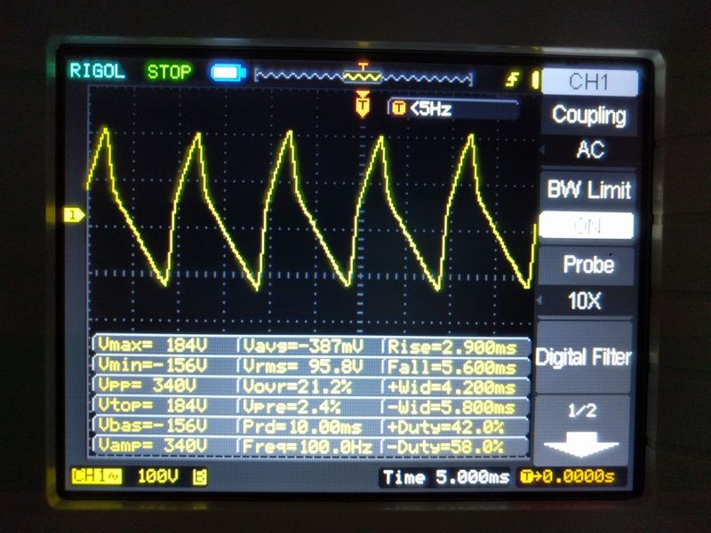
I got twice the mains frequency (230V 50hz) but the trace is weird and seems to yield a negative voltage too...
EDIT: arrrrgh I just realized I took the measure in AC Coupling, no wonder the traces and measures are bonkers ......stupid
Thanks for all those extensive informations 😉
however, I thought that first capacitor value was not so crucial in the case of a choke input filter (as in my amp topology).
Else, the 5Z3P is given with the same first filter capacitor value limit as the 274b (datasheet-> http://www.mif.pg.gda.pl/homepages/frank/sheets/095/5/5Z3P.pdf )
and it works absolutely no problem on my amp for hours long.
Still it seems the amp is draining a bit to much current from the 274b.
I posted a scope measurement of my 5Z3P rectifier earlier and the trace seems odd to me, shouldn't it be a semi-sinus with only positive voltage and twice the mains frequency?
I got twice the mains frequency (230V 50hz) but the trace is weird and seems to yield a negative voltage too...
EDIT: arrrrgh I just realized I took the measure in AC Coupling, no wonder the traces and measures are bonkers ......stupid
Last edited:
Still it seems the amp is draining a bit to much current from the 274b.
I think that if the problem is an overloading in the rectifier, then I must suppose that both sections of it must be overloaded, not only one. And in such a case, more probably, the plate would be red and not the cathode (over the normal high temperature it works).
Why not just add two resistors to the anodes and then measure and compare volt drop across (using a DVM) and voltages as seen on the scope at the anode. Even something like 2.2 ohms would easily allow a DVM to record the volt drop across them.
Both sides should be pretty equal.
Then compare with the original valve.
You mentioned way back I think that the fuse blew. That maybe suggests the valve shorted internally and put AC across the reservoir caps. I can't see any other scenario that would pop the fuse.
Both sides should be pretty equal.
Then compare with the original valve.
You mentioned way back I think that the fuse blew. That maybe suggests the valve shorted internally and put AC across the reservoir caps. I can't see any other scenario that would pop the fuse.
Measurement done again but in DC coupling
Seems fine to me...
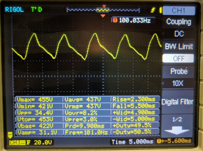
I will return the tube to the seller tomorrow.
Shall I try with a new one? (I really like the light and sound show of this tube)
Seems fine to me...
I will return the tube to the seller tomorrow.
Shall I try with a new one? (I really like the light and sound show of this tube)
You mentioned a Choke input filter in your amp topology (Rectifier, Choke, Capacitor).
(Usually that kind of filter continues on with a Resistor and 2nd Capacitor).
But the Raphaelite CSK30 schematic you posted uses a Capacitor input filter (Rectifier, Capacitor, Choke, Capacitor).
Are you using the original circuit in the schematic, or are you using a choke
input filter?
Before you send the 274 rectifier back, If you have a standalone 5V 3A DC or 5VAC 3A power supply, you can drive the filaments of your questionable 274. Just see if the filaments glow equally, or differently.
OK,
I tried the tube with a bench DC PSU, One of the filament is dead, it doesn't lit and the tube draws only 1.66A at 5V. The tube is busted.
you're right about the input filter, the first component after the rectifier+res(// to regulators) is the first 47uf cap of the double 47uf 500V cap then the choke.
Shall it be possible to:
1. putting a 2.2 or 3.3uf 600v PP cap first, then the choke, then the two double 47uf caps?
2. converting the capacitor input filter to a choke input filter (choke, then first double 47uf cap, then resistor, then second 47uf cap)?
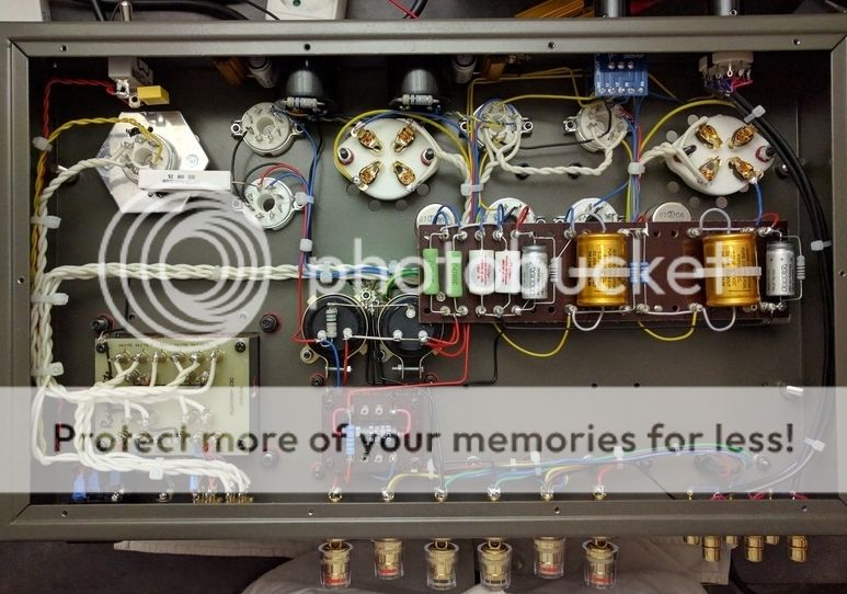
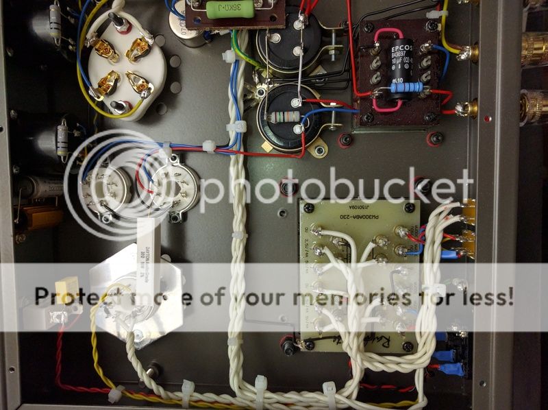
here some picture of the amp innards:
I tried the tube with a bench DC PSU, One of the filament is dead, it doesn't lit and the tube draws only 1.66A at 5V. The tube is busted.
you're right about the input filter, the first component after the rectifier+res(// to regulators) is the first 47uf cap of the double 47uf 500V cap then the choke.
Shall it be possible to:
1. putting a 2.2 or 3.3uf 600v PP cap first, then the choke, then the two double 47uf caps?
2. converting the capacitor input filter to a choke input filter (choke, then first double 47uf cap, then resistor, then second 47uf cap)?
here some picture of the amp innards:
In your first picture both filaments seems to be lit. So this seems like a problem that has occurred since then.
At the end of the day it may just be a duff valve or one that got damaged in transit.
At the end of the day it may just be a duff valve or one that got damaged in transit.
I've tried the amp with a Svetlana winged "C" 5U3C (5U4G) black plates, and it works without any trouble.
The tube will be returned for now.
However, what do you think about changing the capacitor input filter?
I tried a simulation in PSUD
However, what do you think about changing the capacitor input filter?
I tried a simulation in PSUD
As I said in my own thread http://www.diyaudio.com/forums/analogue-source/292628-high-audio-quality-am-tuner.html, I strongly like choke input filter over the cap input.
The trouble is that the inductor designed to work as first element in the filter, must be different for those designed to be the second, ads the AC voltages are very different.
But in any case, I would try removing (temporarily) the resistor at the cathode, shunting the cathode directly to the choke, and removing the firsts cap. You'll get a best supply, surely, but with less voltage at its output.
I suggest to see my thread, the last post.
Cheers.

Well, the 274b seem definitely a no go in my current configuration (far too high first capacitor and a little too high current drain).
The only solution would be to change the input filter (lowering first cap or switching to LC-RC filter) and lowering the overall load of the amp, seems maybe a little overkill.
I found out EML is making mesh plate 5u4G tubes, I may consider trying them.
They are given for max 550V rectified, max 225mA DC current and 40uf max first cap.
My actual first cap is 47uf (a bit more than the max 40uf), shall it work good as is (taking account than my amp draws only something like 170mA at 440V) or should I change the two double 47uf caps for double 32uf ones to prevent the tube to have shortened life?
Will putting lower capacitance lead to a less linearized DC signal or less Voltage?
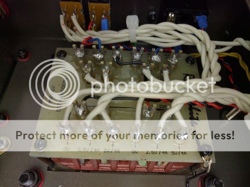
Also, after reading EML application notes ( 5U4G-Mesh and 5Z3-Mesh Data sheet. Emission Labs. ), it seems like my transformer HV winding have too low resistance (77R measured between pin 4 and 6 of the rectifier socket), the 5u4g/5z3p tubes need 170R winding resistance to run correctly.
So I plan to add a 47R 3W resistor on the HV center tap to ground (170-77=93 ->0.5x93=46.5R)
Am I right doing this?
The only solution would be to change the input filter (lowering first cap or switching to LC-RC filter) and lowering the overall load of the amp, seems maybe a little overkill.
I found out EML is making mesh plate 5u4G tubes, I may consider trying them.
They are given for max 550V rectified, max 225mA DC current and 40uf max first cap.
My actual first cap is 47uf (a bit more than the max 40uf), shall it work good as is (taking account than my amp draws only something like 170mA at 440V) or should I change the two double 47uf caps for double 32uf ones to prevent the tube to have shortened life?
Will putting lower capacitance lead to a less linearized DC signal or less Voltage?
Also, after reading EML application notes ( 5U4G-Mesh and 5Z3-Mesh Data sheet. Emission Labs. ), it seems like my transformer HV winding have too low resistance (77R measured between pin 4 and 6 of the rectifier socket), the 5u4g/5z3p tubes need 170R winding resistance to run correctly.
So I plan to add a 47R 3W resistor on the HV center tap to ground (170-77=93 ->0.5x93=46.5R)
Am I right doing this?
Something else is bothering me concerning first capacitor value VS tubes data-sheets.
Until now I tried 3 different rectifiers:
-The one that came with the kit, a 5Z3P witch as a first capacitor value of max 4uf ( much less than the 47uf first cap of the amp, so bad) and a 230mA nominal DC current output (good).
5Z3P datasheet: http://www.mif.pg.gda.pl/homepages/frank/sheets/095/5/5Z3P.pdf
----> Does work fine (but for how long)
-The 274b/n witch ended up busted (because of an internal short or more probably an overloaded current drain), 4uf max first cap (bad) and 98mA nominal DC current output 🙂eek:😱 bad bad bad!!)
It's not the same as normal 274b tube witch are given for 160mA max (better even if not sufficient), if I had known it was that different from the original I would never have bought this tube in the first place 😱
274b/n datasheet: FULLMUSIC-tianjin quanzhen electron tube technology co.,Ltd
274b WE datasheet: http://www.westernelectric.com/spec_sheets/274B.pdf
---->Doesn't work fine at all.....indeed😀
A Svetlana 5µ3C black plates, presented as the russian version of the 5U4G? however, if the 5U4G as a first capacitor limit of 40uf, the 5µ3C, like the 5Z3P has a limit of only 4uf (bad) and a nominal 230mA DC current output (good).
5µ3C datasheet: http://www.drtube.com/datasheets/5c3s.pdf
5U4G datasheet: http://www.r-type.org/pdfs/5u4g.pdf
--->Does work fine (but for how long)
So first; The manufacturer seems to use a rectifier tube in a schematic that overcomes its ratings (concerning the first cap value) or there's something in the amp topology that make it possible (because it just works). How can It be (even more surprising as Raphaelite as a pretty good reputation)
Second: I made a terrible mistake when buying the 274b/n thinking it has the same rating as a normal 274b (my bad only, I think those tubes a more appropriate for pre-amp stages)
Third: contrary to output tubes (a 300b is a 300b, a kt88 is a kt88....) rectifiers of the same type can be really different, depending of your amp current draw and input filter type, you have to be extremely cautious in choosing the right rectifier... Do not trust equivalence claiming without deep datasheet reading.
so now In my current configuration, I only have two RELIABLE choices:
-a true 5U4G (old sylvania or better a EML mesh plate one, for the quality and the freaking look)
-a 5AR4/GZ34 (small, ugly but beefy)
EDIT: I tried with a 5AR4 from another amp, as expected it takes a little time to bring B+ to full (indirect heating) but I got nasty sounds for 2sec during the WY2p regulator heating (before they started right away), but I noticed that the 300b biased now at 70mA against 60mA before, so the 5AR4 are spitting more B+
If I want to use something else, or even the 5Z3P and 5µ3C I'm using now reliably, I need to do modification on the capacitor input filter, right?
Last edited:
Well, I took some times researching a solution to make my psu more rectifier friendly, here what I found:
First the original schematic
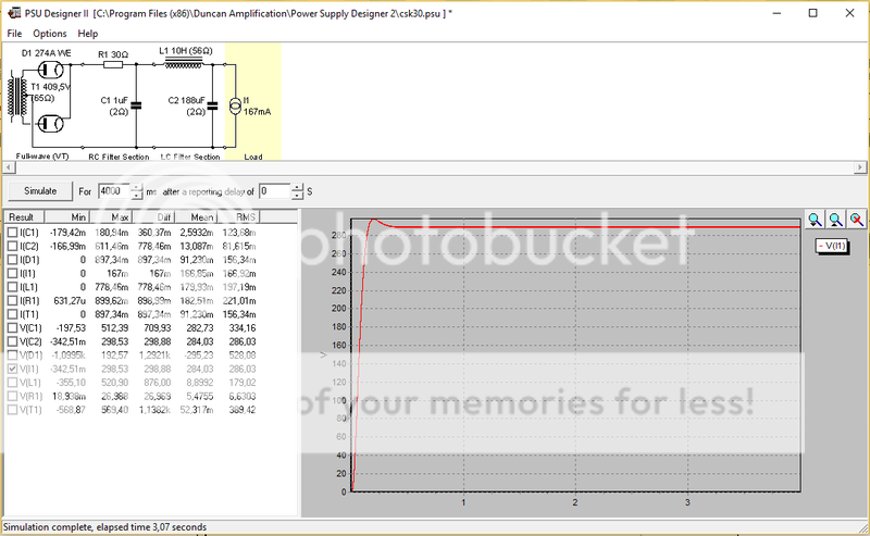
And the simulation in PSUdesigner (green is voltage, red current)
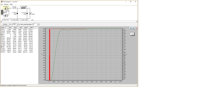
not so bad, but a little bump in voltage and the mighty 47uf first cap
Now a new simulation with some parts values modifications:
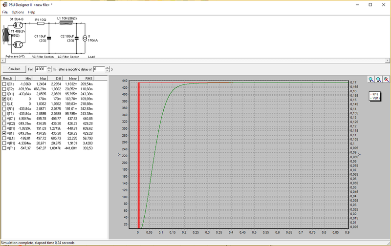
Seems much better and with only a 10uf as first cap.
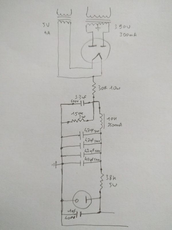
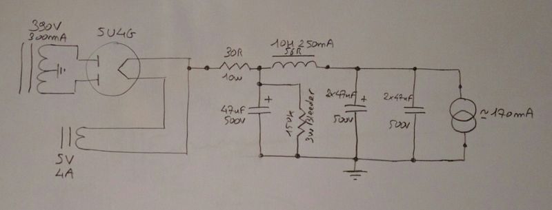
Here the two modified schematics I came out with:
1
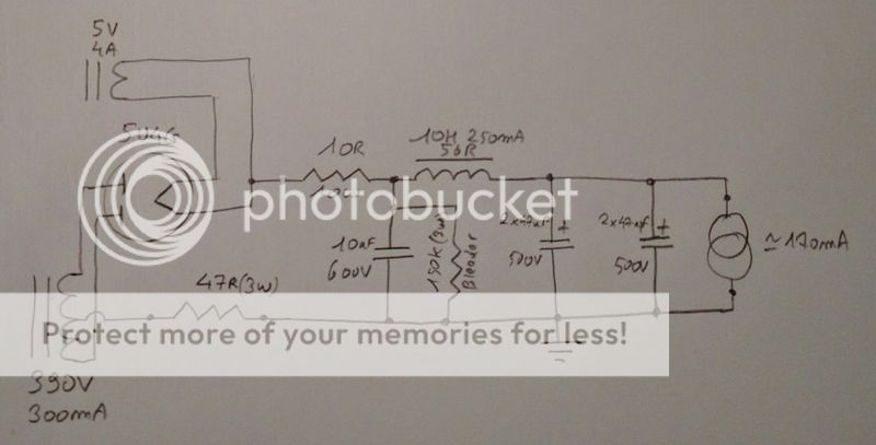
With the 10uf first cap and a 47r res in series with the HT center tap for higher plate winding impedance.
2
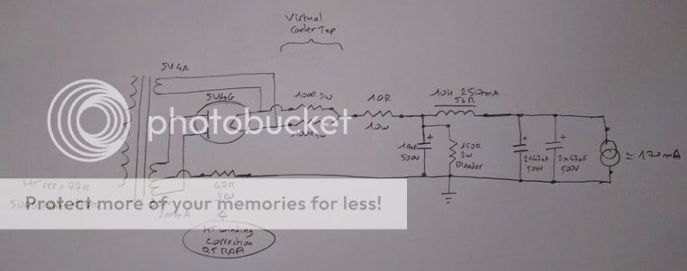
Same as the first one, but with the addition of a virtual center tap for the filament winding (idea taken from the Emissionlab 5u4g data-sheet), I don't know if this is right like this.
First the original schematic
And the simulation in PSUdesigner (green is voltage, red current)
not so bad, but a little bump in voltage and the mighty 47uf first cap
Now a new simulation with some parts values modifications:
Seems much better and with only a 10uf as first cap.
Here the two modified schematics I came out with:
1
With the 10uf first cap and a 47r res in series with the HT center tap for higher plate winding impedance.
2
Same as the first one, but with the addition of a virtual center tap for the filament winding (idea taken from the Emissionlab 5u4g data-sheet), I don't know if this is right like this.
- Status
- Not open for further replies.
- Home
- Amplifiers
- Tubes / Valves
- Is my 274b/n defective