Originally Posted by krivium
Camplo could you point to time to peak energy/ gd curves in your thread please i missed that.
Is it possible to cover the whole spectrum, high spl, low distortion with a 2-way?
Ah ok, thank you Camplo.
The way you formulated it in the other thread confused me, but yes gd can be seen as a kind of stored energy, hence the peak at max gd appearing in the sonogram.
The way you formulated it in the other thread confused me, but yes gd can be seen as a kind of stored energy, hence the peak at max gd appearing in the sonogram.
...An old Tom Danley forum post, with parts i think that fit that discussion......
> > Hi all
> >
> > I am not sure how many Joes are in the "its all magic" camp and how many
> > are interested in how things really work but so far as how a woofer
> > really works, this has been known for some time. Authors like Benson,
> > Heyser have written very good books and papers on the subject.
> > At least from being able to model / predict the performance of a real
> > speaker from its electroacoustic equivalent circuit, there are no
> > missing links or mysteries, just a few things mfr.'s chose not to
> > explain and or things some choose not to look at..
> > Perhaps this explanation will help.
> >
> > The number one misconception about woofers is that moving mass has
> > something to do with "speed" of response or its high frequency limit.
> > It does not, at least directly.
> > What mass effects is efficiency and also the shape of the low frequency
> > roll off.
> >
> > A radiator that is small compared to the wavelength it is producing,
> > experiences an increasing acoustic load with increasing frequency (one
> > of the few places on sees a frequency dependent resistance with out a
> > reactance). That radiator in an infinite baffle, driven at a constant
> > velocity
> > will produce a +6 dB oct rising response because its radiation
> > efficiency increases with frequency.
> > To make a driver like this have "flat response", we must roll off the
> > voltage response 6 dB per octave, one pole.
> > This is done by having a much larger amount of mass or weaker motor such
> > that above some point velocity control is lost and then with increasing
> > frequency, the velocity falls 6 dB oct. It is this range, where the
> > velocity falls 6 dB /oct that one has flat response.
> > Electrically, this speaker looks like and acts like an R/C filter, the R
> > is the coil R+the amplifier source R and the C is the moving mass of the
> > speaker reflected through the motor, which looks /acts like a capacitor.
> >
> > Since the moving part is the C, it is the voltage across it (the voltage
> > /velocity output) which falls 6 dB /oct, which is canceled out by the
> > changing radiation resistance and now gives flat response. The -90
> > degree phase shift of the slope is not canceled out as the radiation
> > resistance is pure resistance. Changing the size of the C (moving mass)
> > has no effect on the slope angle, just its level and starting point.
> >
> > 99% of the people do not realize that when a point source has flat
> > response, its mid band acoustic phase lags behind the input signal by
> > about -90 degrees (once all fixed time delays are accounted for). This
> > broad band lag is equal to a time delay who's amount increases with
> > decreasing frequency. This -90 degree operation is how some of the
> > simpler measuring systems "determine" acoustic phase, it is a Hilbert
> > transform of the amplitude and at low frequencies for a simple piston,
> > this is a safe assumption.
> >
> > Consider how a normal "perfect" speaker spreads out a signal in time.
> > Make an imaginary signal that has equal amplitude content from 100 Hz to
> > 25 Hz, a specific waveshape which has this property.
> > Take an imaginary perfect flat response speaker who's upper and lower
> > cutoffs are way past our needed bandwidth.
> > This mass controlled "flat" response speaker has a -90 degree lag or
> > delay, at 100 Hz the phase shift is equal to a source 2.83 feet behind
> > the speaker cone, at 50 Hz, the delay is equal to 5.66 feet, at 25 Hz is
> > equal to 11.32 feet and so on.
> > This test signal's wave shape defines the input "time" of each frequency
> > component.
> > When reproduced, the highest frequency component at 100 Hz emerges from
> > the radiator 2.5 ms AFTER the signal arrived at the driver terminals.
> > At 50 Hz, this component emerges 5 ms AFTER the signal hit the terminals
> > and at 25 Hz, the signal emerges after 10 ms and so on.
> > With the driver spreading the signals frequency components out in time,
> > it is simply not possible to retain the same waveshape as the input
> > signal, lower frequencies arrive progressively later in time than the
> > original signal.. Any signal reproduced is done so with the spectrum
> > rearranged in time by the drivers acoustic phase response.
> >
> >
> > If one had a driver which had a very strong motor or a normal motor but
> > very low moving mass, one gets an "over damped" response.
> > This term is from filter design meaning that it is not optimally flat,
> > excessively damped, rolling off too soon and gradually
> > Should the slope of the response reach 6 dB per octave, the driver is
> > operating in the Velocity controlled mode, while the response is not
> > flat, the acoustic phase DOES track the input signal (zero degrees) and
> > the different frequency components are not spread out in time.
> > The waveshape of the input signal is more closely replicated as the
> > frequency components are in the original "time" although the amplitudes
> > are off 6 dB/oct. Each 3 dB /oct change in the slope produces a 45
> > degree change in phase.
> >
> > An over damped response more closely retains the time information where
> > a flat amplitude response cannot.
> >
> > A proper LF horn can have flat acoustic response AND roughly zero degree
> > acoustic phase.
> >
> > For a person more sensitive to "time errors", they will likely find an
> > over damped system more realistic.
> > For a person more sensitive to "amplitude errors" the traditional "flat
> > response" system will be more satisfying.
> > For the person lucky enough to have heard a proper lf horn system, you
> > have heard that one can have "lightning fast" sounding bass and still
> > make your pant legs flap.
> >
> > A normal "flat" response point source speaker HAS this kind of delay
> > built right in and it is unavoidable (currently).
> > All conventionally driven point source speakers MUST have the phase
> > shift / delay if they are to have flat frequency response (dictated by
> > the falling velocity, acceleration controlled response needed to offset
> > the changing radiation resistance with frequency).
> >
> > Additional reactance's can alter this phase relationship.
> > For example above midband at the point in the impedance called Rmin, the
> > electrical series "L" is equal but opposite the reflected moving mass
> > (capacitive reactance) of the driver thus canceling each out and being
> > resistive (no phase shift).
> > Above that frequency, the series Inductance dominates and produces a
> > roll off with an inductive reactance.
> > At the bottom end to the response, for a simple sealed box, there is a
> > point where the parallel spring or "compliance" of the box and driver
> > are equal but opposite the moving mass and this point is also resistive
> > (at box resonance). Below that frequency, the spring constant dominates
> > (an inductive reactance) and the acoustic phase leads
> >
> > More complications from non perfect drivers and alignments..
> >
> > In pro sound it is a common practice to evaluate subwoofers with a kick
> > drum signal.
> > Such a signal has a wide spectrum however it makes a bad test signal for
> > a subwoofer alone.
> > Nearly always, the subwoofer with the best "snap" or attack is the one
> > with the greatest distortion and or the highest low cutoff.
> > Clearly, the ear hears the added hf content and judges it to be more
> > lifelike.
> > In actual operation, the subwoofer is mated with midbass speakers who's
> > job it is to produce the spectrum above the subwoofer.
> > Now, with the actual drum signal being produced in the upper ranges, the
> > subwoofers formerly desirable distortion spectrum interferes with the
> > real drum signal. Now, the subwoofer with the least distortion will
> > often have the best subjective sound.
> >
> > A subwoofer can be made with a under damped low frequency corner, this
> > puts a bump in the response right before roll off.
> > Subjectively, this can make a woofer sound even slower and the "decay"
> > of the too high Q takes more time.
> >
> > Remember that it is acceleration which produces sound, it is the
> > amplifier current which produces the force which produces the
> > acceleration.
> > While few of you may have a TEF machine or are able to measure real
> > acoustic phase, most of you can plot the current phase angle with
> > respect to the voltage drive signal for a woofer. The phase shift curve
> > of the current vs freq will have the same shape as the acoustic phase
> > shift (although the degrees are different). If one had a speaker that
> > was flat midband, one could look at the current phase in that range and
> > assume the acoustic phase magnitude was about -90 deg .
> > This acoustic phase IS time, it is essentially ignored in discussions
> > about how speakers sound, yet it accounts for most of what you guys and
> > others are talking about.
> >
> >
> > Tom Danley
I need to read into more of what is said here but the part I underlined...I think it fits the description of the approach to Acoustic Elegance drivers? Non the less, a very nice perspective on things...
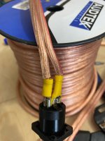
I couldn't let anything like that exist in my equipment 😉I think this will fly...
I can recommend uninsulated crimp connectors and some heatshrink over the top.
The back of the crimp digs in to the wire insulation as a secondary lock.
5-160431-2 | TE Connectivity, FASTON .187 Uninsulated Spade Connector, 4.75 x 0.51mm Tab Size, 1mm2 to 2.5mm2 | RS Components
The pliers needed to make a nice job of the crimping can be had from any auto parts store or online.
Why would you spend all that money on drivers, birch ply etc and then butcher your interconnects. If you want to solder why not solder the bare wire straight to the speakon and slip some heat shrink further up the cable jacket so you can pull it down to cover after soldering.
It's simple, you tin the wire, you tin the connector, put some solder on your iron tip and bring them together with some heat. Crocodile clips or other clamps to hold the two pieces in place. Flat pliers or haemostats are helpful to hold the wire and avoid burning your fingers.
Thanks for the info, wish I had of asked first...
I hooked up the datv3 and after a bunch of head scratching, I think I've overfilled the box with density 80...qts read .9 and the impedance peak at 80ohms....for a box slightly under 230 liters thats impossible.
I hooked up the datv3 and after a bunch of head scratching, I think I've overfilled the box with density 80...qts read .9 and the impedance peak at 80ohms....for a box slightly under 230 liters thats impossible.
Insert the plug into the socket before you solder.
This way the plug acts like a heatsink and helps reduce the chance of overheating the socket tab so that you get a bit more rise time to avoid melting the socket's plastic body, if that makes sense....
This way the plug acts like a heatsink and helps reduce the chance of overheating the socket tab so that you get a bit more rise time to avoid melting the socket's plastic body, if that makes sense....
Another tip: make sure the two parts you are soldering stay put exactly how you like them to be, and dont have tension to them, before you solder. It is difficult to solder if the parts disconnect the second you touch them with the iron, or are already disconnected before you start. The alligator clip helper /extra hand can be annoying sometimes, altough necessary. Happy soldering 🙂
Overfilling would usually result in the Q being lower and the shape of the impedance peak looking weird.I think I've overfilled the box with density 80...qts read .9 and the impedance peak at 80ohms....for a box slightly under 230 liters thats impossible.
Well how the heck do I have a Q of 0.9? The only thing I can think is that the 16ohm voice coils have completely different specs than the 8 or the 4ohm version. I'll take the free air specs...later today I guess. I couldn't even make the qtc reach 0.9 in horn resp.
You could post the image from dats which may or may not help and a photo of how you have it setup otherwise it is hard to guess.
Camplo... If you can, practice a few times on a spare piece of wire and soldering it to something.
At work I refused to solder for a bit because I was terrified, even though I had been soldering for 20 years. Mostly due to the industry, but what I did find is that every time I did try it, I gained more confidence. It's always a plus to be confident in your abilities, especially if you're a nervous shaker. It was a help to me anyways. Practice makes perfect. Soldering a 30 pin connector with nervous hands wouldn't get many very far LOL.
At work I refused to solder for a bit because I was terrified, even though I had been soldering for 20 years. Mostly due to the industry, but what I did find is that every time I did try it, I gained more confidence. It's always a plus to be confident in your abilities, especially if you're a nervous shaker. It was a help to me anyways. Practice makes perfect. Soldering a 30 pin connector with nervous hands wouldn't get many very far LOL.
For speaker wiring, use the Neutrik Faston crimp connectors fluid showed.
Crimp. No reason to solder....at all, ime.
With 30+ DIY speakers & subs, some spanning over 20 years service....zero problems to date with wiring using crimp connectors.
(mic/line level XLR connectors get solder).
Crimp. No reason to solder....at all, ime.
With 30+ DIY speakers & subs, some spanning over 20 years service....zero problems to date with wiring using crimp connectors.
(mic/line level XLR connectors get solder).
- Home
- Loudspeakers
- Multi-Way
- Is it possible to cover the whole spectrum, high SPL, low distortion with a 2-way?