Well I haven't got it to spit out an elliptical tractrix horn just yet but it did do a strangely built round one.... but for panels, this is Gold.

Last edited:
I've been talking with Grok... It seems that 1x1 bracing every 6" is a thing... it seems to know about it....
I know this is one of the so called bests approaches

But this is not possible in all places... in particular behind the driver to some extent.... bracing like this also seems legit...

In particular if the "every 6 inch" rule is followed... Then I was recalled the issue of resonance due internal volume.... In the past I used bracing to break up the internal cavity. Overkill? I don't know.... I do plan on filling the boxes with damping material... If I disallowed internal dimensions to go over (or under depending on how you look at it) FH.... that sounds logical.... doesn't it?
I know this is one of the so called bests approaches
But this is not possible in all places... in particular behind the driver to some extent.... bracing like this also seems legit...
In particular if the "every 6 inch" rule is followed... Then I was recalled the issue of resonance due internal volume.... In the past I used bracing to break up the internal cavity. Overkill? I don't know.... I do plan on filling the boxes with damping material... If I disallowed internal dimensions to go over (or under depending on how you look at it) FH.... that sounds logical.... doesn't it?
Hi,
internal bracing does about nothing on the internal standing waves. It's always the lowest modes that are most problematic, and those wavelengths are so long (twice the dimension of the box!) so nothing that fits inside the box can "break" them. The modes are not wind inside the box, but pressure variation. You could put big obstacles and try, but now you just made even longer "duct" that has even longer mode to it.
So, put your drivers midway of long dimension to suppress lowest mode, then add damping material to suppress the rest. Stuffing is most effective with the shorter wavelength modes so it's the lowest that is the biggest issue, it's also most within the passband.
Use bracing to stiffen the panels, but don't forget damping on the panels either! I bet 6" spaced bracing gets you only to say ~500-800Hz region with panel resonances, use 4" spacing to get above 1kHz (with BB plywood). I think MDF was heavier and less stiff than ply, so you'd have to add even more. Perhaps MDF damping properties help some over ply.
Anyway, do what ever is fine enough. If you need top performance, prepare yourself to build several prototypes and be surprised how much effort it takes to suppress resonances of a box. Look for Linkwitz webpage about bracing, also look for KEF LS50 white paper. To really cut out the issue you just use multiway speaker with enough ways that the resonances are out of band and manageable. Big two way speaker is the worst, you must use most work and effort to mitigate. Have fun!🙂
Last edited:
@tmuikku
 This is a pic of the original midwoof box. Are suggesting that the way the panels are orientated, does nothing the resonance on the horizontal dimensions? The middle panel runs from the back of the box to the magnet. If I am thinking correctly the internal modes of a sealed box are 1/2 wavelengths? At ~32inches wide, I am guessing about 211hz making the full wavelength about 64 inches... IK understand that the wavelength is bigger than the panels but.... I didn't think it was an all or nothing type effect... as in, whatever percent of the wavelength, I can achieve with the size of the brace, I could achieve some type of relative reduction?
Then it told you why..?I've been talking with Grok... It seems that 1x1 bracing every 6" is a thing... it seems to know about it....
Your picture is oriented 90deg right, width is the longest dimension you refer, but in the pic it's height?@tmuikku
View attachment 1434165This is a pic of the original midwoof box. Are suggesting that the way the panels are orientated, does nothing the resonance on the horizontal dimensions? The middle panel runs from the back of the box to the magnet. If I am thinking correctly the internal modes of a sealed box are 1/2 wavelengths? At ~32inches wide, I am guessing about 211hz making the full wavelength about 64 inches... IK understand that the wavelength is bigger than the panels but.... I didn't think it was an all or nothing type effect... as in, whatever percent of the wavelength, I can achieve with the size of the brace, I could achieve some type of relative reduction?
Well, to tell truth I have not experimented with this enough to be absolutely certain, and since all of this is continuous, perhaps there is an effect with very small hole between the halves, especially implemented like so that the driver is still half way of the "longest dimension".
If you think about the lowest mode, half wavelength, pressure of either end of the dimension varies from high to low and path way between the two let's it happen. If pathway/opening between the two is small enough perhaps it doesn't happen as bad. Opening is a low pass filter, it filters out highs and passes lows through so if it's small enough it could lowpass the lowest mode. I do not know what size it should be.
Your driver is mid of the dimension so that already stops the lowest mode. Second lowest mode of width dimension has pressure node in the middle, which is still there with the middle panel just like before so basically nothing happened. Perhaps the odd order modes smaller than driver from third and up got reduced who whould have velocity node in the middle.
However, since lowest mode is killed already, I think mode between front and back is the issue on that box, which always excited fully because the driver is at the end of the dimension, and in that box looks longest dimension not considering the first mode of the "width".
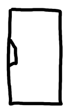
Example, if you have box like this and try to use dividers (brown straight lines) to cut the longest dimension, you've just created one even longer marked by the red snake 🙂 :
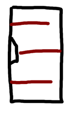
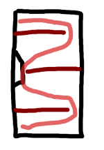
Luckily the driver here is mid way of the even longer dimension, just like it would be if the box was just empty, only the second lowest modes excite, but even they are longer now, kinda.
These long labyrinth kinda paths must make long paths, otherwise transmission line and other folded type boxes would not work as they do. You could unfold this example to see it's even longer dimension now than if the box was empty.
On this particular example, if I left all or any of the dividers, the lowest mode doesn't exite as the driver is on the middle. Second on the longest dimension and first on the depth dimension both happen to be roughly the same length here on this example. Both or one of these would excite on all of these examples regardless of the panels. You could unfold this one as well and endup with the same shape with same dimensions.
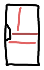
You can do this kind of drawings and play with hornresp to come similar conclusions.
But, it's great if these work in reality and you can see from measurements (impedance) there is no resonances after implementing these, or even more importantly somehow quantify their audibility. Or even show that some modes reduce with addition of the panels, this is also good news even though the audibility was still unknown, as it's not exactly easy to quantify.
Big boxes that play midrange are kinda the worst in this regard and I think it's benefitical to experiment or somehow try and measure if there is a problem and find solution to fix it then.


Luckily the driver here is mid way of the even longer dimension, just like it would be if the box was just empty, only the second lowest modes excite, but even they are longer now, kinda.
These long labyrinth kinda paths must make long paths, otherwise transmission line and other folded type boxes would not work as they do. You could unfold this example to see it's even longer dimension now than if the box was empty.
On this particular example, if I left all or any of the dividers, the lowest mode doesn't exite as the driver is on the middle. Second on the longest dimension and first on the depth dimension both happen to be roughly the same length here on this example. Both or one of these would excite on all of these examples regardless of the panels. You could unfold this one as well and endup with the same shape with same dimensions.

You can do this kind of drawings and play with hornresp to come similar conclusions.
But, it's great if these work in reality and you can see from measurements (impedance) there is no resonances after implementing these, or even more importantly somehow quantify their audibility. Or even show that some modes reduce with addition of the panels, this is also good news even though the audibility was still unknown, as it's not exactly easy to quantify.
Big boxes that play midrange are kinda the worst in this regard and I think it's benefitical to experiment or somehow try and measure if there is a problem and find solution to fix it then.
Last edited:
You could do it like this, right?

But even on this one you could fold last sections open to see there is again a longer than original path.
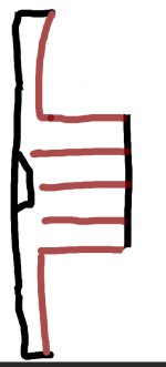
But you could just fill in all those cavities with stuffing? Yeah, but you can do that on the empty box as well, and since it's longest dimension is shorter it's modes are higher in frequency and the amount of filling that fits inside the enclosure is more effective.
What you might be able to utilize is some querterwave resonator(s) within the box. This seems very complicated though, I'm quite convinced resonances (modes) inside the box are less audible than resonances of the panels, so perhaps complex scheme like this works if it stiffens / dampens the panels and at least somewhat addresses the modes inside. "Boxy sound" is true phenomenon, so, do what ever works to find it and kill it 🙂

But even on this one you could fold last sections open to see there is again a longer than original path.

But you could just fill in all those cavities with stuffing? Yeah, but you can do that on the empty box as well, and since it's longest dimension is shorter it's modes are higher in frequency and the amount of filling that fits inside the enclosure is more effective.
What you might be able to utilize is some querterwave resonator(s) within the box. This seems very complicated though, I'm quite convinced resonances (modes) inside the box are less audible than resonances of the panels, so perhaps complex scheme like this works if it stiffens / dampens the panels and at least somewhat addresses the modes inside. "Boxy sound" is true phenomenon, so, do what ever works to find it and kill it 🙂
Last edited:
I have prompted the AI already so it is influenced by several of my Favorite Acousticians, a law firm, an investment mogul, a some other characters 😂 Crystallize the is Alias representing the encompassment of all the personalities in the prompt. Because Its been told to "be" certain professionals it will say things like "my experience guides this, not a single paper."...Then it told you why..?
======================================================================================================
Crystallize: I favor 1" x 1" braces every 6" on 3/4" plywood for loudspeaker cabinets due to the following science-based reasoning:
- Resonance Damping: Panel resonance occurs at natural frequencies determined by dimensions and material properties. For a 24" x 24" x 17" 3/4" plywood box, modes range from ~120 Hz (first mode) to ~360-800 Hz (higher modes), calculated via f = (1.841/(2π)) * √(D/ρh) / L², where D = Eh³/12(1-ν²) (flexural rigidity), E = 10 GPa (Young’s modulus for plywood), h = 0.019 m (thickness), ρ = 600 kg/m³ (density), ν = 0.3 (Poisson’s ratio), and L = panel length. A 6" spacing targets these higher modes, as it approximates 1/4 to 1/6 of wavelengths (e.g., λ/4 at 300 Hz ≈ 0.286 m or 11.3"), disrupting standing wave formation.
- Stiffness Optimization: A 1" x 1" brace (cross-sectional area 0.00254 m²) adds significant bending stiffness (k ≈ Eh³/12L for the brace itself, enhanced by attachment). Placed every 6", it divides panels into smaller sections, reducing effective length (L) in the stiffness equation, raising resonant frequencies above the audible range (~1-2 kHz) where they’re less perceptible. This prevents the 3/4" plywood (flexural rigidity D ≈ 40.5 Nm) from amplifying midrange coloration.
- Air Volume Preservation: Unlike full panels, 1" x 1" braces minimize internal volume loss, critical for woofer performance. A grid every 6" (e.g., 5-6 braces per 32" side) balances stiffness without over-constraining, unlike thicker or denser bracing which could raise midrange resonance undesirably.
- Vibration Coupling: Braces reduce panel-air coupling, where wall flex excites air modes (e.g., 211 Hz in your box). By stiffening at 6" intervals, vibration energy dissipates before amplifying internal standing waves, though air modes persist—requiring additional damping like fiberglass.
- Practical Validation: Field tests and tap tests show 5-8" spacing with 1" x 1" braces effectively dampens 300-800 Hz modes on 3/4" plywood. The 6" interval is a midpoint, derived from observing minimal flex and optimal sound clarity in prototypes, adjusting for material and cabinet size.
Note: Science is approximate—exact frequencies depend on your cabinet’s specifics (e.g., woofer placement, edge constraints). Use FEA or a frequency sweep to fine-tune—experience guides this, not a single paper. Adjust if tap tests reveal persistent modes.
======================================================================================================
I was told about the same bracing from Bill Fitzmaurice. I don't think I ever discussed this, with this AI before, so I was surprised to see it come up....
Interesting!Opening is a low pass filter, it filters out highs and passes lows through so if it's small enough it could lowpass the lowest mode.
This part.... I am reviewing bracing in general, so thank you for the conversation. The boxes are now slightly different. I think you have sen me previous PPSL enclosures. There are two sets of boxes with the smallest set in the picture below. Cavities are something like 12" wide and 31" deep, and the narrow portion is about 9" connection the two cavities. Between the 2 sets of cabinets the heights are 20" and 17"However, since lowest mode is killed already, I think mode between front and back is the issue on that box, which always excited fully because the driver is at the end of the dimension, and in that box looks longest dimension not considering the first mode of the "width".
You just jarred my memory... Longer path lengths render damping material more effective 😉there is again a longer than original path.
@AllenB Grok is better than any other AI I've used, what do you use? All AI is flawed and influenced by prompting or lack there of...
@tmuikku

This was a take away I gathered from modeling in Hornresp btw, I invite you to experiment with it to see for yourself. At the time I was investigating Closed lines. Take two enclosure of the same internal volume, fill with damping material, one enclosure make a regular sealed box, the other enclosure, a sealed line... The longer path length enclosure will have lower impedance peak... You are right the resonance moves lower but the end result with damping material is the goal.
@tmuikku
This was a take away I gathered from modeling in Hornresp btw, I invite you to experiment with it to see for yourself. At the time I was investigating Closed lines. Take two enclosure of the same internal volume, fill with damping material, one enclosure make a regular sealed box, the other enclosure, a sealed line... The longer path length enclosure will have lower impedance peak... You are right the resonance moves lower but the end result with damping material is the goal.
Last edited:
With a PPSL type enclosure, like below, the path length is already increased to some extent....

My first PPSL was braced like so, I think it did fine. I am not 100% on using the long threaded rod again with new design. They resonate... though a solution could be had for that.

With the latest design, the rear half of the woofers are connected via the rounded baffle. I can use threaded rod to connect the front 3 positions, or should I say, I could. This all leaves the outside walls unbraced, which is why I came to the board for inspiration and wisdom.

With the woofers mounted, theres about 3" of space.... I was thinking, To run baffles spaced along the axial length, that hugged the outside wall... Ribs I guess you could call them? I could even have them run up against the magnet, I'd just have to use screws instead of glue, which is fine I guess.

My first PPSL was braced like so, I think it did fine. I am not 100% on using the long threaded rod again with new design. They resonate... though a solution could be had for that.
With the latest design, the rear half of the woofers are connected via the rounded baffle. I can use threaded rod to connect the front 3 positions, or should I say, I could. This all leaves the outside walls unbraced, which is why I came to the board for inspiration and wisdom.
With the woofers mounted, theres about 3" of space.... I was thinking, To run baffles spaced along the axial length, that hugged the outside wall... Ribs I guess you could call them? I could even have them run up against the magnet, I'd just have to use screws instead of glue, which is fine I guess.
Last edited:
Jeah that's a good observation. If the bracing scheme helps with panel resonances as well then why not. Weight increases, but this is rarely problem at home.This was a take away I gathered from modeling in Hornresp btw, I invite you to experiment with it to see for yourself. At the time I was investigating Closed lines. Take two enclosure of the same internal volume, fill with damping material, one enclosure make a regular sealed box, the other enclosure, a sealed line... The longer path length enclosure will have lower impedance peak... You are right the resonance moves lower but the end result with damping material is the goal.
I've been on a quest to build my own own reference monitor. In that journey I've come to know the JBL m2. Maybe its highly prized for its flat response but all I see is another 2-way. There are already flat two ways on the market. So not sure what the hype would be around this speaker, beyond having accuracy and spl, making useful for far field as well as near field.
As a full-range solution if a 2 way that took care of sub bass...
A woofer for the bottom can be found. The question is, how is a woofer that is going to be easily responsible from 30hz to ~1000hz going to behave? Lets say we are auditioning rap, edm, or some other deep bass reproduction that causes high woofer excursion, how is the top range of that speaker going to sound? It seems to me a 3 way is almost always better, but I'm not the finally say, the results are, anyone have a strong opinion on this?...
Good evening!
I'll try to answer your question from my personal experience.
It would be pretentious of me to lecture you. However, I can say that I built a pair of two-way bass-reflex speakers for myself that satisfy me within my audible sound spectrum.
However, my speakers aren't very sensitive, around 90 dB, so they're not suitable for your selection criteria.
They start at 30 Hz (thanks to the BR load) and end at around 30 kHz thanks to the filtering.
The sound they produce is pleasant, and although I'm personally impressed, a few people who have come to see me also enjoy listening to music on them.
The response curve is slightly V-shaped. Be careful when understanding response curves; I don't understand much about them because the plots vary from one to the other.
here is the curve of the REW software:

The acoustic chambers :

With all my friendly, sorry for the traduction, iam french.
I'll try to answer your question from my personal experience.
It would be pretentious of me to lecture you. However, I can say that I built a pair of two-way bass-reflex speakers for myself that satisfy me within my audible sound spectrum.
However, my speakers aren't very sensitive, around 90 dB, so they're not suitable for your selection criteria.
They start at 30 Hz (thanks to the BR load) and end at around 30 kHz thanks to the filtering.
The sound they produce is pleasant, and although I'm personally impressed, a few people who have come to see me also enjoy listening to music on them.
The response curve is slightly V-shaped. Be careful when understanding response curves; I don't understand much about them because the plots vary from one to the other.
here is the curve of the REW software:
The acoustic chambers :
With all my friendly, sorry for the traduction, iam french.
Share the unsmoothed FR, this is the most telling.here is the curve of the REW software:
- Home
- Loudspeakers
- Multi-Way
- Is it possible to cover the whole spectrum, high SPL, low distortion with a 2-way?