Or in other words, a signal that doesn't represent the original signal anymore.
The whole point with data acquisition, is that you don't know what you can expect.
With audio there is no difference.
So that doesn't have anything to do with the fact that somebody was "dumb" (also nice way of describing people fyi).
It's a property of the system.
Why I am saying this?
Well some people here in this topic said that you could "perfectly reconstruct a sine wave with just two samples".
Second is that you don't know how it will be constructed, since you don't know what the original signal was to begin with.
Could be a sine wave with some additional blips, could be a perfect sine wave, could be slightly distorted/compressed sine wave etc.
This is especially true for audio.
Anyway, don't really appreciate when people say somebody is dumb, stupid, lying or unknowing, when somebody clearly is not.
Seen your post history, seems to be a thing that a lot of other people also don't really appreciate.
The only person who can be embarrassed is yourself in that regard.
Your choice to be disrespectful to people.
As for off-topic, this whole topic seems to be literally non-stop off-topic anyway?
It's all over the place and not getting anywhere
Hogwash.
- You can perfectly reconstruct a sine from 2 samples, as long as it's frequency is smaller than 1/2 the sampling frequency Fs. A sine plus any other artifacts (distortion, etc...) is, flash news, NOT a sine.
- If you don't know what the original signal is, you either do a spectral analysis, using a spectrum analyzer, and pick a sampling frequency twice the highest frequency in the spectrum, or you choose a sampling frequency high enough to CYA in the worst imaginable case. Or choose the highest Fs available, it won't harm. For audio, I cannot imagine anything that 100x20KHz=2MHz sampling frequency won't cover. Multiply that by a factor of 10, and it's still ridiculously low today.
- It's not a property of the system (what system, BTW?). It's the Nyquist theorem in action.
- Following your logic, a digital scope cannot be used to show a waveform, since one doesn't know what signal comes at it's input. How is that for "dumb"?
Any unpleasant feeling could be avoided if you would listen, acknowledge what it is said, understand your errors, and stop victimizing yourself. Errare humanum est, sed perseverare diabolicum.
Lesson is over.
Last edited:
omg, i'm jumbling my own words now, thanks. ignore my defensive word salad in the last post.
I actually think this thread has stayed on topic much better than many that have reached this length and the question posed by it can only really contain subjective answers, so its bound to be all over the place.
I actually think this thread has stayed on topic much better than many that have reached this length and the question posed by it can only really contain subjective answers, so its bound to be all over the place.
Here is an interesting table from Doug J. Button, Design Parameters and Trade-Offs in Large Diameter Transducers 😉
Camplo,
This is the packet on the Nyquist sampling theorem one of my best ever instructors (formerly of Texas Instruments.....
The Nyquist Sampling Theorem
Thank you both!
Yes, thanks for that Brinkman. an easily digestible text format explanation to match the youtube. I'll be refreshing myself, so I can talk/communicate with more confidence on the subject next time.
The packet doesn’t delve into the trigonometric identities involved (the student was expected to have concurrent or prior trig classes), nor does it really get detailed in regards to aliasing and guardband but it does drive home that it is the DC offset of the sampling frequency waveform that preserves the “original” sampled signal which is thus extracted via the reconstruction filter. It’s just so very clever; I am really enjoying reviewing it and really regret not completing my EET certification.
To make this post a little more germane to the OT, here’s a video of Bill Waslo testing his Small Syns loudspeaker’s ability to resolve a square wave: Square Wave sweep as played by SmallSyns loudspeaker (in-room) - YouTube
To make this post a little more germane to the OT, here’s a video of Bill Waslo testing his Small Syns loudspeaker’s ability to resolve a square wave: Square Wave sweep as played by SmallSyns loudspeaker (in-room) - YouTube
Last edited:
My response was in reference to the configuration you quoted from Art which was 1 metre CTC and 100Hz to 400Hz.If we actually going debate it, lets be specific. To be fair I'll stick with the same theoretical config that inspired the topic
This is a very different situation to that which may best reflect what you intend. Certainly the lower you push the crossover the less the CTC distance matters which is hardly news to anyone.
The point is how the drivers combine together over what distance. It is quite possible in a DSP based system to have multiple configurations optimized for the various distances of listening and switch between them but one optimized for 1m will not sound the same at 3m or vice versa.Theres nothing left to do but linearize phase for the desired listening position with DSP. At almost any distance, this can only be corrected for one spot (some attempt to average over a span of areas) aka as "head in vice" and within the criteria above correcting phase should lean towards good results at 1meter or 3, for the use of the above config. If you disagree, whats the science behind your reason.
Drivers behave differently in the near field and the far field and the bigger the driver the further out in distance that will be.
Nearfield monitors are by and large small speakers so that the drivers integrate well at short distances and the drivers don't need to be so big as they can get loud enough at the short listening distance. The form of the device is following it's intended function.
I think the JBL M2 is an impressive DSP driven 2 way. SOTA? Opinions vary.
Rob🙂
Except it’s really a three way, on account of the coaxial CD.
(Sorry to be OT🙂
The JBL D2 seems to be dual diaphragm device but it is just one band, both diaphragms playing the same. Made for high SPL PA systems it seems.
thats what I thought too and you could indeed drive it that way, but I believe in the case of the M2, it is driven differentially, with one diaphragm opposing the other to cancel even order distortion at high spl.Except it’s really a three way, on account of the coaxial CD.
(Sorry to be OT🙂
The JBL D2 seems to be dual diaphragm device but it is just one band, both diaphragms playing the same. Made for high SPL PA systems it seems.
That's how I now understand it as well.
Could you guys point to a source of this or is it conjecture?
Edit: Actually forget about it. It’s a dual ring radiator dual phase plug device, to extend bandwidth without the need for an expensive Be diaphragm. It’s based on the BMS coax ring radiator but different enough to carry it’s own patent.
Anyhow it’s really splitting hairs to call it a two way device and it’s not really a coax like I stated.
I stand corrected🙂
Last edited:
It's not conjecture it is a dual diaphragm driven by the same signal.Could you guys point to a source of this or is it conjecture?
Brochure
http://www.linkwitzlab.com/M2_Brochure_Jan2013.pdf
and wiring seen here
Attachments
The brochure says 2 way with an XO of 800 Hz: https://jblpro.com/en-US/site_elements/m2-brochure (PDF download)
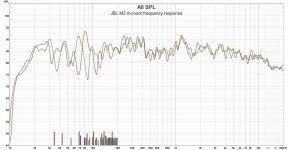
I have a few in-room measurements of the JBL M2 from different rooms. Here is one example with 1/12 octave smoothing:

Legit 20 Hz to 20 kHz operation. DSP/DRC can smooth the frequency response as desired.
Erin, aka @bikinpunk has run the full gamut of JBL M2 loudspeaker measurements, including polars at: JBL M2 Master Reference Monitor
I have a few in-room measurements of the JBL M2 from different rooms. Here is one example with 1/12 octave smoothing:
Legit 20 Hz to 20 kHz operation. DSP/DRC can smooth the frequency response as desired.
Erin, aka @bikinpunk has run the full gamut of JBL M2 loudspeaker measurements, including polars at: JBL M2 Master Reference Monitor
Attachments
Last edited:
Could you guys point to a source of this or is it conjecture?
I stand corrected🙂
So did I, but not before publicly calling it a gargantuan misnomer. My words; something like 'An 'active' 2 way speaker, that is actually a 3 way; does not include any amplifiers, DSP, active, or passive crossovers, yet still weighs and costs as much as a small car. Not so much an active speaker, rather an incomplete speaker.'
Egg on face when I found out it was a different version of the driver.
I knew they called it a 2 way, but it wouldn't have been the first time there was truth lacking in audio advertising and I was savoring the irony of that specification. :redface:
Last edited:
It's not conjecture it is a dual diaphragm driven by the same signal.
Brochure
http://www.linkwitzlab.com/M2_Brochure_Jan2013.pdf
and wiring seen here
Yes, dual ring radiator / dual phase plug / dual voice coil - BUT a common electrical connection. I’ll be less sloppy when splitting hairs in the future😉
It may have even been fluid that corrected me at ASR, or rather saw what had caused my conflation ... i'm skeptischism on there. 😛
For mechanical driver to enclosure, less membrane weight will result in less acceleration of the enclosure but for pressure interaction it will be equal to s heavy cone.
//
Yes. I don't think many people realize this.
Now let's imagine a 15" woofer of 150 grams doing 500 Hz versus a CD of around 1 to 2 grams doing it.
Imagine the enclosure reaction, the total surface area reacting?
It is many times the 15"..
Except it’s really a three way, on account of the coaxial CD.
(Sorry to be OT🙂
Well no it's a 2 way both diaphragm's are driven by the same output from the DSP active crossover
Rob🙂

- Home
- Loudspeakers
- Multi-Way
- Is it possible to cover the whole spectrum, high SPL, low distortion with a 2-way?