for good reason ....
The Supermicro units I recommended are quieted workstation versions that use tachometer controlled fans. The harder you work the MPUs the louder they get. WHG
Thanks for the info. Not a problem for me to configure it or even build it as required. It looks like I have a few options for stock machines that could sit as a compute server in the basement so I wouldn't have to hear it. 🙂
Offloading the sims to another machine will work (I do this with @docali) but you need a proper ABEC license so the solution (solve) file can be returned. We were fortunate enough to get a license under non commercial hobbyist terms from Joerg Panzer @ R&D-Team - Software Development
The Supermicro units I recommended are quieted workstation versions that use tachometer controlled fans. The harder you work the MPUs the louder they get. WHG
The Supermicro units I recommended are quieted workstation versions that use tachometer controlled fans. The harder you work the MPUs the louder they get. WHG
Is the one you say in the same range as SYS-7049GP-TRT?
I have this and its madness. Its not the case fans, its the two PSUs with the 40mm super-fans that go crazy.
Am I missing some setting?
I have 3 dual xeon systems with 80ish threads each. I can spin WIN/Linux VM and run sim if you need help. just PM me.
My sims usually take a month on 80 threads /100% so no problem with temperatures.
I realized I added the ABEC license issue to the wrong post, it was intended for you w.r.t the compute offer. Thanks.
"Offloading the sims to another machine will work (I do this with @docali) but you need a proper ABEC license so the solution (solve) file can be returned. We were fortunate enough to get a license under non commercial hobbyist terms from Joerg Panzer @ R&D-Team - Software Development"
Ok guys, legit question regarding aperiodic transmission lines. The line itself dampens the resonance...so for that reason, deadening the enclosure has less importance and thinner walls can be used for construction right? In question is putter baffle walls and inner line folding walls. I was thinking 3/4” outer but was wondering could you get away with 1/4” walls inside...I had plans on using 1/2” inside on line folding....but really couldn’t I use 1/2” everything and just double up on the driver baffle?
Material is Baltic Birch
Material is Baltic Birch
Hmmm
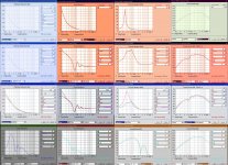
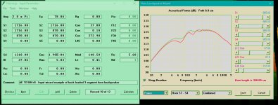
ps- 3rd row, input was lowered on the larger TL to match displacement.
ps- 3rd row, input was lowered on the larger TL to match displacement.
Attachments
Last edited:
As effective motor strength [Qts'] declines, the more lossy the cab can be, so some of us have successfully used glued together Celotex, Masonite, Styrofoam or similar panels of varying thickness with only something a bit stronger to mount the typically low power 'FR' driver. For heavier, more powerful drivers, these are typically mounted to a basic box frame OB. Any bracing is strictly for supporting a heavy driver and/or moving it around.
In short, let the cab 'breathe'/damp as much as practical rather than relying solely on mass quantities of stuffing.
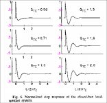
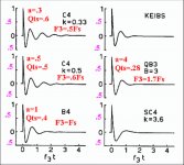
Note that as George. L. Augspurger proved, a Fs/Qts' alignment works well for ~aperiodic TLs: http://diyaudioprojects.com/Technical/Papers/Loudspeakers-on-Damped-Pipes.pdf
Rick Shultz's Alpha TL realization: http://diyaudioprojects.com/Technical/Papers/Alpha-Transmission-Lines.pdf
GM
In short, let the cab 'breathe'/damp as much as practical rather than relying solely on mass quantities of stuffing.
Note that as George. L. Augspurger proved, a Fs/Qts' alignment works well for ~aperiodic TLs: http://diyaudioprojects.com/Technical/Papers/Loudspeakers-on-Damped-Pipes.pdf
Rick Shultz's Alpha TL realization: http://diyaudioprojects.com/Technical/Papers/Alpha-Transmission-Lines.pdf
GM
SWAG: Fan Match Issue
The Model you reference has more air handling.
The MPU fans must be 4-pin, PWM units to match the others in your system.
Use Super Doctor 5 to monitor system temperature gradients.
If problem not resolved, contact SM Tech Support. They have been helpful to me in the past with configuration and additional parts issues.
Regards,
WHG
Is the one you say in the same range as SYS-7049GP-TRT?
The Model you reference has more air handling.
I have this and its madness. Its not the case fans, its the two PSUs with the 40mm super-fans that go crazy.
Am I missing some setting?
The MPU fans must be 4-pin, PWM units to match the others in your system.
Use Super Doctor 5 to monitor system temperature gradients.
If problem not resolved, contact SM Tech Support. They have been helpful to me in the past with configuration and additional parts issues.
Regards,
WHG
Last edited:
Are there any rules about spacing the back of the driver from the back wall of an enclosure?
- if Im reading this correctly then I don't think it will matter.Most offset transmission line speakers place a reflective wall fairly close behind the transducer within the enclosure – posing a problem for internal reflections emanating back through the transducer diaphragm. Older descriptions explained the design in terms of "impedance mismatch", or pressure waves "reflected" back into the enclosure; these descriptions are now considered outdated and inaccurate as technically the transmission line works through selective production of standing waves and constructive and destructive interference
Last edited:
"...Posing a problem for internal reflections emanating back through the transducer diaphragm..." - well if I were to take this statement as truth, and find myself in a bind, looking at GM's recent post, "Celotex, Masonite, Styrofoam" is a perfect candidate for this portion of the line, as a solution. Thanks Gm, perfect timing. =)
If anyone has more charts like these please share.
The qtc is closed box and the qts is bass reflex
If anyone has more charts like these please share.
The qtc is closed box and the qts is bass reflex
Attachments
Last edited:
If you can take the size (huge), a Klipsch Jubilee (Jubilee bass horn + K402 mid horn) is a two way that reproduces the full spectrum with unlimited headroom, very high SPL and fantastic SQ.
I don't know the masurement conditions of thsi one here:
https://community.klipsch.com/uploads/monthly_10_2013/post-14473-13819304418308.jpg
But I guess that neither the K-Horn nor the Jubilee bass horn are "as fullrange" as desired by the OP. I belive nonetheless that the Jubilee would be great fun to listen to (as is the K-Horn which I have personal experience with) but it wouldn't be usable as studio monitor I fear.
Regards
Charles
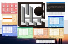
By coincidence the TL that actually fits into my size goal vs the slightly larger TL I designed as ideal... the former is more efficient.
Smoother too.
Does anyone have literature on Impedance Curve levels vs perception....I wonder whats the point of diminishing return. My design has really low impedance. Its safe to say that less impedance/resonance is always better in order to draw a line in the sand, but maybe its not so clear cut.
Impedance has a frequency response. Best evaluated with the amplifier of choice as the amplifier may or may not be a good choice for a given speaker.
I'd be surprised if there is any scientific controlled tests done on the audibility of impedance wiggles in isolation. Toole mentions resonances are audible and should be dealt with. Don't remember what page in his book that is shown though.
I'd be surprised if there is any scientific controlled tests done on the audibility of impedance wiggles in isolation. Toole mentions resonances are audible and should be dealt with. Don't remember what page in his book that is shown though.
Impedance has a frequency response. Best evaluated with the amplifier of choice as the amplifier may or may not be a good choice for a given speaker.
I'd be surprised if there is any scientific controlled tests done on the audibility of impedance wiggles in isolation. Toole mentions resonances are audible and should be dealt with. Don't remember what page in his book that is shown though.
The Impedance curve is exactly how you monitor the enclosure resonance isn't it? So if I have several systems with a resonance peak at 80hz....and one shows as 80ohms and another 40ohms and another 20ohms...obviously the lesser the ohm spike the lower the resonance but whos to say that anything below 80ohms you cannot perceive a change vs a particular sealed alignment with an impedance peak at 140ohms thats obvious.
I need some type of bearing. The TL above has a 20ohm peak which is probably as low as it should be, but it would be nice to see what the studies say.
Impedance has a frequency response. Best evaluated with the amplifier of choice as the amplifier may or may not be a good choice for a given speaker. Toole mentions resonances are audible and should be dealt with. Don't remember what page in his book that is shown though.
This is the chapter about impedance versus amplifiers (damping factor) versus loudspeaker cable.
Attachments
- Home
- Loudspeakers
- Multi-Way
- Is it possible to cover the whole spectrum, high SPL, low distortion with a 2-way?