The gasket on the front face helps it to be a horn driver..
Ahhh, so it most used as horn driver mounted from behind?
How does it look from the frontside, have you also pics at that?
Did you send frds and zmas of all the drivers? Or at least single mid-woofer (frd and zma) and tweeter (frd and zma)?
Last edited by a moderator:
Did you send frd's and zma's of all the drivers? Or at least single mid-woofer (frd and zma) and tweeter (frd and zma)?
Yes
Here it is again Lojzek.
Regards John
Attachments
What is the estimated Z-offset (tw-midwoofer)?
I'm not familiar with that expression, and actually don't know exactly what it means. Could you explain?
This is only my 2 speaker that i am building, so i don´t "know" more than some basics and that i will use the Audax HM210Z10 as high up as possible but don´t hear much beaming.
Maby try out cross at 2,1-2,2 K
I have driver parameters if that helps
Regards John
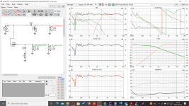
Nevermind that for now. This is a response based on your files, Z-offset=0; x/o filter as designed by yourself.
There seems something wrong compared to your simulated graph.

There seems something wrong compared to your simulated graph.
Nevermind that for now. This is a response based on your files, Z-offset=0; x/o filter as designed by yourself.
There seems something wrong compared to your simulated graph.
With this filter ?
Don´t understand, now when i put the same value in again it don´t show the same response ??
Must be the laptop at that time, Virusprogram wanted to re-start....and sometimes laptop acts strange when that happens.
And i know also see that i have fill in "scaling" -5 dB.
So sorry Lojzek
Last edited:
Correct, that one. Single 210 Z10 is 91-92 dB @ 1.2kHz. Two of these in parallel should be +6dB.
Correct, that one. Single 210 Z10 is 91-92 dB @ 1.2kHz. Two of these in parallel should be +6dB.
Yes
Its so strange?
Must have laptop problem at the time or a VituixCAD in some bugg-mode?
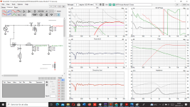
This is the filter you use for that resoponse, right ?
ANd kow i get the same response as you Lojzek!
VituixCAD must have the response from only 1 midrange in that earlier response.
Last edited:
Hi knowelege hifi people
Has any of this the 2 xover "better" data an the other?
Want to cross at 2,1-2,2 K, and are greatful for coments because i don´t have the skills to "read out" all data.


Best regards John
Has any of this the 2 xover "better" data an the other?
Want to cross at 2,1-2,2 K, and are greatful for coments because i don´t have the skills to "read out" all data.
Best regards John
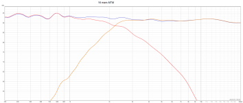
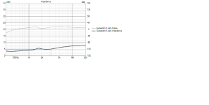
Change the 110dB SPL box to 95dB so you can see how transfer functions look below 70dB. This way you have look into what going above and below crossover point, eg. if the cone break ups are attenuated sufficiently. You can also increase or decrease vertical resolution. If you click on the driver box the X is the horizontal offset, Y is the vertical (up or down from 0 reference) relative to microphone, Z moves the driver back and forth and has largest impact on how the 'phases' of each driver relate to each other. If you flip the polarity of the tweeter it should show a null in the freq resp. If you measure it should show similar null, if not you 'allign' untill they are close the measured. In your build, since it' a MTM only Z really matters. Double clicking on inductor box allows you to change wire size and resistance of the coil. The glitch around 1.5k in freq resp of the filter and in impedance curve is most likely cone-edge resonance of the Audax, impedance looks very OK. Clicking on impedance graph allows to add Equivalent Peak Dissipation Resistance, which is impedance with the capacitive and inductive element of the phase angle combined - more real life representation of what the class AB amp sees at the terminals. Clicking on driver freq resp will allow to set Optimizer transfer function, say to LR2, LR4, BW3, for Axial response - basically you will see how much you're off from 'textbook perfect' slope. Other than that since the midbass in 8" cone, I would try lower than 2kHz xover (if the tweeter allows) to avoid directionality mismatch - a hole in power response (room response) at and below xover. And it's kind of bad idea to place resistor in series with mids/woofers, unless they operate only as mids and above 200-300Hz. I usually set my tweeter level 2-3dB below midwoofer for smooth out transfer between drivers (the loss of energy from the midbass caused by directivity, resonances) - I prefer Sennheiser over Beyer Dynamic headphones 😉 - so maybe the 2.4ohm resistor is not needed at all. Also resistor would change the Qes, Qts of the driver.
ASR forum has some diy projects where they used off axis Klippel data to put attention at the directionality, room response, crossover issues. Also Erin measured two kits from PE and put the driver so people can play with CAD and possibly design better versions of the kits for themselves 😉
ASR forum has some diy projects where they used off axis Klippel data to put attention at the directionality, room response, crossover issues. Also Erin measured two kits from PE and put the driver so people can play with CAD and possibly design better versions of the kits for themselves 😉

hange the 110dB SPL box to 95dB so you can see how transfer functions look below 70d
.I don´t have the skills for what you ask for, bur this is 95 dB scale.
Regards John
95dB is way better. the two boxes on the right from 95dB - one decreases the dB resolution, the one beside "Ovl" increases it. The + saves the graphs as overlays so you can compare what happens if some thing gets changed in xo. You just play with it and you will become a PRO 😉 in options you can change the scale for impedance, filters 'dB', ect. It's amazing a CAD like this is available to DIY people for free.
I have experience with that HM210Z10. It has rather bad breakup modes above 2k, which should be avoided if you want a non-fatiquing sound. I have crossed it at 1.5k 2nd order with an elliptical slope. Once the breakup modes are buried under 10 dB compared to average system SPL, you won't really notice them.
Nowadays I prefer the B&C 8pe21 compared to any other 8" mid drivers. It can be used up to 3k and can rip off your face if called upon (in a good way). Its a unicorn of a driver.
B&C 8pe21 and Eighteen Sound 8M400 seems very "the same".
Have you heard the 18 sound 8M400 ?
http://www.loudspeakerdatabase.com/18Sound/8M400
@jawen
Just judging by measurements, the 8PE21 is a more balanced and well behaved midrange transducer.
I would also take a look at Faital Pro's selection of 8" they added some interesting and reasonable ones this year like the 8fe400.
Worth to take a look here :
https://www.dibirama.altervista.org...-sound-8m400f-mid-range-8-8-ohm-320-wmax.html
The 18sound is similar but not as refined higher up in FR as the 8PE21 IMO. The THD is lower and the Qts supports better performance in FLHs.B&C 8pe21 and Eighteen Sound 8M400 seems very "the same".
Have you heard the 18 sound 8M400 ?
http://www.loudspeakerdatabase.com/18Sound/8M400
- Home
- Loudspeakers
- Multi-Way
- Is an almost flat impedance curve a big advantage in terms of sound quality in DIY projects