
KEF was famous for (in my book anyway...) having "burner" components in the crossover. "Burner" meaning they did nothing except flatten the impedance looking into the speaker. Belief was amplifiers behave better when loaded into flat Z; their speaker model may see many different amps and they wanted to load them all uniformly, to minimize amp "rolling".
Flat impedance really required if you chose to use an amplifier with high Rout. A voltage amp will not care (unless low impedance overwhemlmed the amplifiers ability to deliver current.
Since some of the best sounding amplifiers i have heard fall into the high Rout class, i think flat impedance is a laudble goal.
dave
Yes, this is the same as when the driver impedance varies and you need to make up for it in the crossover... so if the amp has it's own output impedance (although most do not, ie it's near zero ohms), it can change the response. This might be good or not. You can't change the amp but you can fix the whole speaker impedance variations.
Some people don't even do that.. they just use EQ instead.
Some people don't even do that.. they just use EQ instead.
like high Q resonances (like the one in the Audax) and directivity
Can you explain what tells you high Q resonanses in my Audax HM210Z10 ?
Something in the mesaurement ?, specs ?
And why it is "bad" ?
Regards John
Your filter may be high Q, the capacitor is large and the inductor is small, it may be taking in more energy at resonance than needed.i have the same small irregularity both on respons and impedace.
Last edited:
(although most do not, ie it's near zero ohms)
In the retail market probably in excess of 99% of amplifiers have very low output impedance, but here in diyLand with, in particular, SE amplifiers both SS & tubes with highish output impedance have a significantly higher penetration here.
Of particular importance if the OP finds himeself drawn to a apir of ACAs (ie diy intro to “firstwatt”).
dave
So if that causes the response to be different, it will sound different for that reason. The difference may not be large, but can be seen using the simulator to add the amplifier output impedance.
Different consequences for different approaches, for example:
1. If OP sets the amp output impedance in Vituixcad to the same as the ACA, the designed crossover and any future changes will always work properly when used with the ACA.
2. If OP leaves Vituixcad at the default setting but designs a conjugate circuit for the impedance, the crossover will be correct for any amplifier, but you will need to modify the conjugates every time you update the crossover.
The Q value of a resonance can be said to express how sharp the "peak" is. So a very pointy / sharp peak is a high Q resonance as opposed to a soft wide bulge in the frequency response is a resonance with low Q. Your little blipp at 1k is more of the first kind.Can you explain what tells you high Q resonanses in my Audax HM210Z10 ?
Something in the mesaurement ?, specs ?
And why it is "bad" ?
Regards John
High Q resonance are "ringy", like a bell. They sound bad and require equally sharp filters to mitigate - sharp filters are hard to design and implement. Low Q resonances more change the tone/timbre of the "party" and are much easier to EQ and thus, tame.
So when looking for bad things in a spl or impedance trace, big broad deviations from a flat, horizontal trace are "OK" but sharp, thin ones should be avoided.
//
The Q value of a resonance can be said to express how sharp the "peak" is. So a very pointy / sharp peak is a high Q resonance as opposed to a soft wide bulge in the frequency response is a resonance with low Q. Your little blipp at 1k is more of the first kind.
High Q resonance are "ringy", like a bell. They sound bad and require equally sharp filters to mitigate - sharp filters are hard to design and implement. Low Q resonances more change the tone/timbre of the "party" and are much easier to EQ and thus, tame.
So when looking for bad things in a spl or impedance trace, big broad deviations from a flat, horizontal trace are "OK" but sharp, thin ones should be avoided.
Thanks for explaining TNT
Now i understand why you thought it was "high Q resonanses"
If you look at my mesaurements without passive filter and with passive filter, do you still thought it was "high Q resonanses" at 1k ?
Its more hard to seems to fix the the irregularities at 750 hz.
Regards John

Last edited by a moderator:
Your filter may be high Q, the capacitor is large and the inductor is small, it may be taking in more energy at resonance than needed.
Thank you for explaining AllenB
Are you refering to both filters ?
Or combination 11,6uF/ 0,390mH and 0,640mH/17uF, or combination 13,6uF/ 0,390mH and 0,720mH/32uF ?
Regards John
I saw a woofer response in post#13 and a circuit in post#16. The thing with this is the response is up and the impedance was down. So I calculated the frequency then I calculated the Q.
You would need to confirm one way or the other, but that should be simple.
You would need to confirm one way or the other, but that should be simple.
I was solely talking about:
Ahh, you mean that.
Yes it´s hard to get completely awy, but don´t know "how much" that is okey.
This is one filter and you still se the "nick", but it´s more even.
Is it going to be a problem you think ?
And this other filter with 3-4 more dB sensitivity.
Bigger "nick" but don´t know if its to big?
Regards John
Present your case with full data, all the files including and you will receive your answer
Okey Lojzek and others, now i have taking all the mesaurements on mid´s and tweeter without filter in REW from 1 m.
Was going crazy and have spend 5-6 hours figured out whats going on left and right MTM showing different dB´s even without any passive filter 🤔.
It showed up that it was 1 of my XLR cabels who did 3-4 dB lower mesaurements......Grrrrrrr
As i have a 11 channel preamp, aktive filter and 2 amp´s....It was trickey to find the problem
Always believed it was the different passive filters which I worked with!
In what smooting should i make the files?
Use Var smooting ?
Regards John
I saw a woofer response in post#13 and a circuit in post#16. The thing with this is the response is up and the impedance was down. So I calculated the frequency then I calculated the Q.
You would need to confirm one way or the other, but that should be simple.
Ahh, okey.
#13 was pic from VitiuxCAD whit "normal" filter component placements.
#16 Was when i put the voltage source/amp in serie with the tweeter, and had a 400.000 ohm resistor at amp "placement in VituixCAD
EDIT: Now first i get it.....1+1 is 2 hahaha...You are right AllenB
Regards John
Last edited:
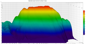
Here is a different view of the 1,5k resonance and the corresponding waterfall.
It looks rather benign on some measurements and others it is quite obvious depending on X/Y axis impedance scaling.
It is not as high Q as the typical breakups in hard cone drivers, like seas excel etc. But it 'rings' for some time as visible in the waterfall, but the amplitude dies down rather fast.
The cone is more damped too then harder cones, but it might be objectionable, depends on the ears that listens.
it's in the natural passband, from your measurements is not much to do about it.
chrome-extension://efaidnbmnnnibpcajpcglclefindmkaj/https://en.toutlehautparleur.com/media/catalog/product/datasheet/audax/HM210Z10-8.pdf
Last edited by a moderator:
Here is a different view of the 1,5k resonance and the corresponding waterfall.
It looks rather benign on some measurements and others it is quite obvious depending on X/Y axis impedance scaling.
It is not as high Q as the typical breakups in hard cone drivers, like seas excel etc. But it 'rings' for some time as visible in the waterfall, but the amplitude dies down rather fast.
The cone is more damped too then harder cones, but it might be objectionable, depends on the ears that listens.
it's in the natural passband, from your measurements is not much to do about it.
Hi Arez and thank you for your participation.
In today´s mesaurement the waterfall for the Audax HM21010 looks like this.
Regards John
Attachments
I venture to guess that is not a outdoors measurements with huge space around or a anechoic chamber?
If not your response gating is way too high according to the pic, to get much info from the CSD when it comes to the resonance behavior. you will have a lot of time for artefacts to creep in.
try a gating of 5-10 ms.🙂
I have no experience with that particular driver, i only added some info from measurement/datasheets i found.
So if it is objectionable/noticeable i cant tell, and all our ears are different with different defects.
- Home
- Loudspeakers
- Multi-Way
- Is an almost flat impedance curve a big advantage in terms of sound quality in DIY projects