Here is another measurements of the same driver, just note that the CSDs are taken with a 50db scale not 25 as most does.
https://www.dibirama.altervista.org...udax-hm210z10-mid-range-8-8-ohm-240-wmax.html
Compare it to this, similar sized Audax which has a more typical high Q resonant behavior like the hard cones drivers, a long ragged tail above 2K that use a long time to die out in amplitude. this peak would likely deserve a notch filter to not be noticeable if used in that bandwidth. Still the amplitude is not as bad as hard cone drivers.
https://www.dibirama.altervista.org...-audax-hm210z2-woofer-8-8-8-ohm-140-wmax.html
And lastly the 10".
This is marked as a woofer, decent efficiency and not too heavy. It would no doubt be objectionable if you want to cross it over at 1500+, which it is clearly not suited for.
https://www.dibirama.altervista.org/home-page/woofer/311-audax-ht240m0-woofer-10-8-ohm-160-wmax.html
chrome-extension://efaidnbmnnnibpcajpcglclefindmkaj/https://en.toutlehautparleur.com/media/catalog/product/datasheet/audax/HT240M0-8.pdf
And a old seas 10" driver from the same page, that shows what a real bad high Q resonance issues looks like, you can see how the amplitude does not reduce at all after 4ms, and keeps on.
https://www.dibirama.altervista.org/home-page/woofer/319-seas-l26rfx-p-woofer-10-8-ohm-300-wmax.html
Theyre new and damped cones of course, behave much better in that regard.
Here is the files, and the VituixCAD save with filter
Its 1 Audax HM210Z10 and 1 Mundorf AMT, mesaured in my room from 1 meter ( acoustic timing reference: Timing offset 4ms (1,372m) Whatever that means)
Havent used 2,83 Volt in mesaurements, but use the same signal volyme. ( don´t know how to get exactly 2,83 V)
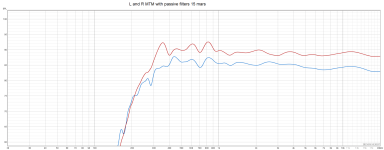
The last pic is a mesaurement from the Left and Right MTM with the 2 different passive filters, one of them is the autual xover in the VituixCAD fil, even if VituixCAD show a different response. ( Ivé separated them for more easy study)
PS! Buy the way, i use 6 Peerlees XXLS 830847 up to 340 Hz with active filter, 3 each side. ( just so you know)
Best regards John
Its 1 Audax HM210Z10 and 1 Mundorf AMT, mesaured in my room from 1 meter ( acoustic timing reference: Timing offset 4ms (1,372m) Whatever that means)
Havent used 2,83 Volt in mesaurements, but use the same signal volyme. ( don´t know how to get exactly 2,83 V)
The last pic is a mesaurement from the Left and Right MTM with the 2 different passive filters, one of them is the autual xover in the VituixCAD fil, even if VituixCAD show a different response. ( Ivé separated them for more easy study)
PS! Buy the way, i use 6 Peerlees XXLS 830847 up to 340 Hz with active filter, 3 each side. ( just so you know)
Best regards John
Attachments
Last edited:
Compare it to this, similar sized Audax which has a more typical high Q resonant behavior like the hard cones drivers, a long ragged tail above 2K that use a long time to die out in amplitude. this peak would likely deserve a notch filter to not be noticeable if used in that bandwidth. Still the amplitude is not as bad as hard cone drivers.
Do you mean this at The Audax Z10 ?
Or this at the Seas
I venture to guess that is not a outdoors measurements with huge space around or a anechoic chamber?
If not your response gating is way too high according to the pic, to get much info from the CSD when it comes to the resonance behavior. you will have a lot of time for artefacts to creep in.
try a gating of 5-10 ms.🙂
I have no experience with that particular driver, i only added some info from measurement/datasheets i found.
So if it is objectionable/noticeable i cant tell, and all our ears are different with different defects.
And no, the mesaurements is from my room in the basement. ( 5 x 10 M hight ca 2,47 m )
Learning to use REW and to do mesaurements, still have to learn about "gating"
Thanks for telling me about it 🙂
The Italian site was interesting, and strangely I have an older spec Audax HM130Z0 from there 👍
John
I venture to guess that is not a outdoors measurements with huge space around or a anechoic chamber?
If not your response gating is way too high according to the pic, to get much info from the CSD when it comes to the resonance behavior. you will have a lot of time for artefacts to creep in.
try a gating of 5-10 ms.🙂
I have found the setting for gating i REW, what settings do you recomend? ( Settings in red cirkle)
John

Try lowering rise time to 0,1 ms
Time range can be longer, i use 10 ms.
Also, I use nearfield measurement for waterfall diagrams. Farfield seems to include several resonances that do not cone from the driver - but maybe i am mistaken.
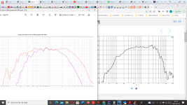
Played a little in REW, and this is rise time 0,1ms, time range 10ms. ( but many other settings is avalible, like total slices and Perspective settings )
But mesaurement is from 1 meter on Left MTM with passive xover how works from 340 hz and up, crossed at ca 2K
And this is only midrange raw in my room without any xovers also from 1 meter ( i cross them at 2K later)
Don´t know if its good or bad.
Regards John
Last edited:
I've experienced time and time again that inductor quality shows itself being quite audible in the lower mids where the LF driver tends to have the lowest impedance and places the highest current demands on the amp. The reflected (distorted) EMF through a poor quality LP inductor (powdered or ferrite core) causes the amp to react in an unlinear fashion if it can't absorb the EMF and keep it from getting back into its own NFB loop. Good transistor output stage amps won't show any issues in this scenario but most valve amps with low damping factor will have problems here.
A low quality ferrite core inductor itself will introduce rather large amounts of audible distortion in the lower mids and it gets worse the lower the impedance dips with the higher resulting current going through the LP filter. Always use the largest stacked iron core or better yet, air core inductor you can afford. The wire qauge isn't important with an air core inductor, as long as the DCR is correct for the application and power limits aren't exceeded. Air core coils don't saturate at all but the cross talk can be substantial if the current is high, so place them accordingly in the crossover layout. Also avoid ferrous metal in close proximity to air core coils. This will cause distortion as opposed to close by non-ferrous metals lowering (dampening) the inductor value. I build all my crossovers on plywood boards and avoid metal fasteners wherever I can, especially in the middle of air core coils.
A low quality ferrite core inductor itself will introduce rather large amounts of audible distortion in the lower mids and it gets worse the lower the impedance dips with the higher resulting current going through the LP filter. Always use the largest stacked iron core or better yet, air core inductor you can afford. The wire qauge isn't important with an air core inductor, as long as the DCR is correct for the application and power limits aren't exceeded. Air core coils don't saturate at all but the cross talk can be substantial if the current is high, so place them accordingly in the crossover layout. Also avoid ferrous metal in close proximity to air core coils. This will cause distortion as opposed to close by non-ferrous metals lowering (dampening) the inductor value. I build all my crossovers on plywood boards and avoid metal fasteners wherever I can, especially in the middle of air core coils.
I've experienced time and time again that inductor quality shows itself being quite audible in the lower mids where the LF driver tends to have the lowest impedance and places the highest current demands on the amp. The reflected (distorted) EMF through a poor quality LP inductor (powdered or ferrite core) causes the amp to react in an unlinear fashion if it can't absorb the EMF and keep it from getting back into its own NFB loop. Good transistor output stage amps won't show any issues in this scenario but most valve amps with low damping factor will have problems here.
A low quality ferrite core inductor itself will introduce rather large amounts of audible distortion in the lower mids and it gets worse the lower the impedance dips with the higher resulting current going through the LP filter. Always use the largest stacked iron core or better yet, air core inductor you can afford. The wire qauge isn't important with an air core inductor, as long as the DCR is correct for the application and power limits aren't exceeded. Air core coils don't saturate at all but the cross talk can be substantial if the current is high, so place them accordingly in the crossover layout. Also avoid ferrous metal in close proximity to air core coils. This will cause distortion as opposed to close by non-ferrous metals lowering (dampening) the inductor value. I build all my crossovers on plywood boards and avoid metal fasteners wherever I can, especially in the middle of air core coils.
Hi profiguy
Lower mids mean 100-300 hz ?
Is this "problem" related also to a system that use an active filter to splitt upp the frequency from the preamp in "under 340 hz" and over 340 hz.
And send all frequency under 340 hz direct to the stereoamp which feeds the woofers without any other filter.
And send all frequency over 340 hz to the stereoamp which feed the MTM, ho has a passive filter crossing att 2 K ?
I wanted the amps to only "work" in used frequencies, and not waste power on frequencies it still does not deliver.
regards John
Also, don't use the gray colored JB weld epoxy around air core coils. It has iron powder as filler in it, which affects the inductance in a bad way.
The distortion issue in the lower mids (few hundred hz) applies to passive LP filters).
Active xovers don't have this issue not being affected by impedance swings of drivers.
This is another reason why active xover is better for lower frequencies, as the amp only reproduces the intended frequency range and doesn't require expensive components.
The only downside is placing active components in the signal path, potentially adding more noise and distortion. Higher quality active crossovers can be expensive compared to passive filters, even with large coils and caps needed for lower frequencies. I prefer analog active xovers, which make things even more expensive if you want very good SN ratios and low THD.
Also, don't use the gray colored JB weld epoxy around air core coils. It has iron powder as filler in it, which affects the inductance in a bad way.
Have begain to mesaure all filter components, and it´s damn what big differences it is!
A 36uF was 32uF..okey....But 22 was 17,8Uf, 15 was 13.....3,9 was 3,2 and so on
The air coils also is shitty, 0,68mH was only 0,634, 1 mH was 0,9, 1,1 was 0,967 and so on.
Hard to just pick one with the right value written on it.
Be careful relying on inductance and capacitance testing meters. Most of them have a large tolerance.
The only downside is placing active components in the signal path, potentially adding more noise and distortion. Higher quality active crossovers can be expensive compared to passive filters, even with large coils and caps needed for lower frequencies. I prefer analog active xovers, which make things even more expensive if you want very good SN ratios and low THD.
Looked for a long time for both analog and digital active xover, try to read a lot but diden´t end up with any.
A panic buy was the cheep DBX 234xs from Thormann
https://www.thomann.de/se/dbx_234_xs.htm
But someday i will look for a good one, can you recomend some in differant priceclasses?
Be careful relying on inductance and capacitance testing meters. Most of them have a large tolerance
Don´t say so hahaha, i allready have so many error-points-variabels in my DIY.
Using a old LCR from 1998, but don´t know how exact it is!
https://www.tme.eu/en/details/chy24cs/lcr-meter/chy-firemate/
| Inductance measuring accuracy | ±(5% + 3 digits) |
| Capacitance measuring accuracy | ±(2% + 10 digits) |
| Resistance measuring accuracy | ±(0,3% + 1 digit) |
I have experience with that HM210Z10. It has rather bad breakup modes above 2k, which should be avoided if you want a non-fatiquing sound. I have crossed it at 1.5k 2nd order with an elliptical slope. Once the breakup modes are buried under 10 dB compared to average system SPL, you won't really notice them.
Nowadays I prefer the B&C 8pe21 compared to any other 8" mid drivers. It can be used up to 3k and can rip off your face if called upon (in a good way). Its a unicorn of a driver.
Nowadays I prefer the B&C 8pe21 compared to any other 8" mid drivers. It can be used up to 3k and can rip off your face if called upon (in a good way). Its a unicorn of a driver.
That shows your LCR meter measuring on the low side, which is common. Once you know this, you can obviously deduce the component values from that and use it to match L and R pairs.Have begain to mesaure all filter components, and it´s damn what big differences it is!
A 36uF was 32uF..okey....But 22 was 17,8Uf, 15 was 13.....3,9 was 3,2 and so on
The air coils also is shitty, 0,68mH was only 0,634, 1 mH was 0,9, 1,1 was 0,967 and so on.
Hard to just pick one with the right value written on it.
I have experience with that HM210Z10. It has rather bad breakup modes above 2k, which should be avoided if you want a non-fatiquing sound. I have crossed it at 1.5k 2nd order with an elliptical slope. Once the breakup modes are buried under 10 dB compared to average system SPL, you won't really notice them.
Nowadays I prefer the B&C 8pe21 compared to any other 8" mid drivers. It can be used up to 3k and can rip off your face if called upon (in a good way). Its a unicorn of a driver.
I have looked at 8pe21 many times, and they have some similarities in measurements...Difficult with an octagonal shape only, how did you do a nice mounting?
Attachments
Would really appreciate your input on my diy project
And sorry guy´s i forgotten to send also ZMA files for the project, here is everything.
In room mesaurement FRD tweeter, midrange, BUT but the manufacturer's impedance files.
And 1 VituixCAD file with data.
Best regards John
And sorry guy´s i forgotten to send also ZMA files for the project, here is everything.
In room mesaurement FRD tweeter, midrange, BUT but the manufacturer's impedance files.
And 1 VituixCAD file with data.
Best regards John
Attachments
The gasket on the front face helps it to be a horn driver..Difficult with an octagonal shape
- Home
- Loudspeakers
- Multi-Way
- Is an almost flat impedance curve a big advantage in terms of sound quality in DIY projects