most left (first of six) is -no input relay being engaged- , so Mute
deliberate, on top of it
I'm looking at pictures, thinkin of making short list of things to check
deliberate, on top of it

I'm looking at pictures, thinkin of making short list of things to check
Checked all calibration again, Voltage, bias, offset, all seems good…
I tried running a single channel at a time and connected to only a single channel on the amp as well, same buzz on both channels, but left seem to be a little bit louder.
I’ll try some other things tonight and then wait for your suggestions.
In the end, I wouldn’t be surprise it would be something stupid… LOL
Do
one thing you can try, even if it isn't highly logical - try replacing those coax cables with simple twisted triplet of wires
do that on one input section and on output, then test that side for hum
short list of things to check:
-proper rail voltages (+/-12Vdc)
-proper Iq of buffers (20mV across 1R resistor)
-proper output offset of buffers ( as close to 0mV as you can set)
-no continuity between two channel grounds, I mean - value of 2 NTC in series
-each channel GND to chassis - value of one NTC
-absolutely no continuity between channel GNDs and relay PSU (nor GND nor positive)
Hey ZM! 🙂
All the mentioned items have been checked several times, including yesterday
-proper rail voltages (+/-12Vdc) = all good
-proper Iq of buffers (20mV across 1R resistor) = all good
-proper output offset of buffers ( as close to 0mV as you can set) = all good
-no continuity between two channel grounds, I mean - value of 2 NTC in series = all good
-each channel GND to chassis - value of one NTC = all good
-absolutely no continuity between channel GNDs and relay PSU (nor GND nor positive) = all good
As for the cabling, it is not coax but two wire silver interconnect with drain wire and shield. I'm using the drain wire as gnd. Used this many times before with no issues but will replace wires.
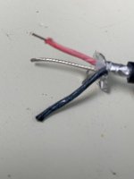
As per my pictures (not the one in this post but the ones in Dropbox), the output is using simple twisted wire triplets for balanced and simple twisted dual wire for unbalanced. However, output from buffers to transformers is the interconnect type wire, which I will change.
I'll let you know my findings.
Thanks
Do
All the mentioned items have been checked several times, including yesterday
-proper rail voltages (+/-12Vdc) = all good
-proper Iq of buffers (20mV across 1R resistor) = all good
-proper output offset of buffers ( as close to 0mV as you can set) = all good
-no continuity between two channel grounds, I mean - value of 2 NTC in series = all good
-each channel GND to chassis - value of one NTC = all good
-absolutely no continuity between channel GNDs and relay PSU (nor GND nor positive) = all good
As for the cabling, it is not coax but two wire silver interconnect with drain wire and shield. I'm using the drain wire as gnd. Used this many times before with no issues but will replace wires.

As per my pictures (not the one in this post but the ones in Dropbox), the output is using simple twisted wire triplets for balanced and simple twisted dual wire for unbalanced. However, output from buffers to transformers is the interconnect type wire, which I will change.
I'll let you know my findings.
Thanks
Do
Last edited:
I resume you're using red as Pos, white as Neg and Black as GND
just in case :
GND - pin 1
Pos - pin 2
Neg - pin 3
is shield electrically connected to Black?
just in case :
GND - pin 1
Pos - pin 2
Neg - pin 3
is shield electrically connected to Black?
Pinout is all good
The black cable is for negative, red positive and silver wire is the drain wire electrically connected to foil shield, used as gnd.
This is from my cable picture above. This is gauge 20 or 22, not sure. I have some older cable which was used back in the days for P2P in 80’s computer stuff, wire would wrap around chip long socket legs… I believe gauge 30, so very tiny but I don’t know the quality and if the gauge is big enough and good for this purpose….
I already desoldered and XLR inputs and just need to change wire from buffer to transfos.
I’ll wait your ok on this.
Do
if not bother, try it
I said, changing coax is not logical but you obviously have some gremlins there
also, tidy those safety GND wires - no need for separate wire to pcb mounting hole, nor isolator
put proper metal riser there, so pcb is connected to case through bolt and riser
I said, changing coax is not logical but you obviously have some gremlins there
also, tidy those safety GND wires - no need for separate wire to pcb mounting hole, nor isolator
put proper metal riser there, so pcb is connected to case through bolt and riser
de-soldered all cables including PSU, cleaned the underside of the PCB, then inspected everything again.
Put back everything inside the chassis but only connected one RCA input on each side. For the output decided to connect the transformers on the main PCB as per the pads and XLR/RCA on the PCB as well instead of connecting everything to the transformer PCB. then checked proper gnd connectivity with NTC and chassis, etc...
Then came the R-Core transformers. Powered up everything but there was still some noise but way lower... I also noticed the measuring the NTC before, it was 12.5 ohms and now 11 ohms (all measured at same ambient temperature after an hour or so not touching or powering). So cleaning up the board might have helped in some ways with residues being a little conductive.
I then decided to use external toroid transformers and then the already lowered noise was absolutely absent on the right channel and very low on the left channel.
I think I might have nailed it with your help and lots of patience... Yes real freakin' patience! LOL
I'll be re-assembling everything including XLR cables I had since they don't seem to have made a difference at all.
I'll keep you posted!
Do
Gremlins man
As I told you, my builds are totally silent, with donuts inside box
same pcb, same everything
btw. value of NTC isn't critical - anything in range of 10-27R will do
As I told you, my builds are totally silent, with donuts inside box
same pcb, same everything
btw. value of NTC isn't critical - anything in range of 10-27R will do
LOL! How many names do I have 
I had used the donuts before today on the outside but it was not making any difference, so something has changed for sure... Maybe there was conductive flux, maybe a solder bead, maybe maybe... But now, with donuts still on the outside, it is totally silent.
I just need to order a nice encapsulated donut transformer from Toroidy like below I guess?
2x 15-0-15 - 10VA each
1x 24-0-24 - 20VA
I plan on buying your remote controlled volume, so I populated the logic section.
Please send me an email with pricing for the remote volume control.
Thanks man for all your help and patience!
Do

I had used the donuts before today on the outside but it was not making any difference, so something has changed for sure... Maybe there was conductive flux, maybe a solder bead, maybe maybe... But now, with donuts still on the outside, it is totally silent.

I just need to order a nice encapsulated donut transformer from Toroidy like below I guess?
2x 15-0-15 - 10VA each
1x 24-0-24 - 20VA
I plan on buying your remote controlled volume, so I populated the logic section.
Please send me an email with pricing for the remote volume control.
Thanks man for all your help and patience!
Do
That was a marathon, Wow!
Fantastic work Do and ZM, lots of patience for sure. Now you can enjoy Quiet Pumpkin while waiting for your Toroidy trafo’s.

Fantastic work Do and ZM, lots of patience for sure. Now you can enjoy Quiet Pumpkin while waiting for your Toroidy trafo’s.

oh well... I thought I had finally fixed it but seems like SE --> SE works perfectly but SE --> BAL gives huge hum/buzz when I start increasing the volume. The first 6-7 are pretty quiet but the noise goes up as the volume goes up. At max volume it is super loud.
I will need to try BAL --> BAL and see if it makes a difference or not.
Too bad because this things sounds just phenomenal. I really need to fix this...
Do
I will need to try BAL --> BAL and see if it makes a difference or not.
Too bad because this things sounds just phenomenal. I really need to fix this...
Do
well, do you have a scope?
you need to check rails and try to chase where buzz origin is ...... considering that ( due to problems with destructive Customs) you did all soldering by your self, including JFets - I can expect that there is some systematic mistake, resulting in same problem on both channels
I can't see any problem on pictures you sent me
when you set SE in channel, is 6th relay on channel energized?
first check both rails on both channels
if anything suspicious - get pictures of gigglywiggly here
good if you get practically flat DC
if anything suspicious - get pictures of gigglywiggly here
good if you get practically flat DC
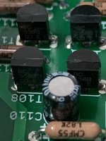
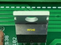
Before I go any further, just want to show you some pictures of the CCS BJTs and Mosfets, just so we know for sure all is good. I was able to grad the part number on them. I followed the silkscreen but don't actually know if they're proper pinout. Do you remember what you sent me if the pinout matches the silkscreen?
Here's for the positive rail :
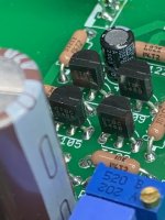

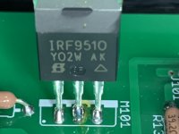
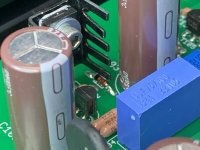
Negative rail :
Next I'll measure on AC coupling positive and negative rails
Thanks
Do
Here's for the positive rail :


Negative rail :


Next I'll measure on AC coupling positive and negative rails
Thanks
Do
- Home
- Amplifiers
- Pass Labs
- Iron Pumpkin(s) and other smaller vegetable animals, Tips 'n' Tricks thread
