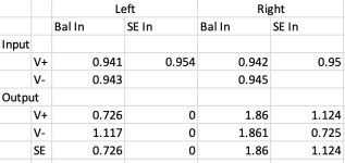
take any source ( PC prog or whatever), set 1Khz sine to arbitrary level - say 1Vac as seen on your DVM
set vol to max.
feed that signal to input of pre
measure what you got on output
do the same for both SE and bal inputs
measure both SE and Bal outputs
write what you got here
note - for said test all you need is any signal source and decent DVM; as you're measuring ratio between two (same) signals, no need for ultramegagiga measuring setup
reminder
1Vac in SE In will give 2Vac SE out and 4Vac Bal out
1Vac to Bal in will give 1Vac to SE out and 2Vac to Bal out
if you don't have means to give Bal signal, try feeding pin 2 and pin 3 with your SE signal (no connection to pin1/GND), taking care that source is floating ...... meaning free of safety GND
battery operated PC/laptop is good for that

This is worse than I'd hoped. Obviously I've screwed something up with SE inputs on the left board. Was it like this forever? I can't say, but it's like that now. I ran two tests that produced identical results. I'll do some reading in the thread about SE inputs, but I wanted to post the results. Yeesh.
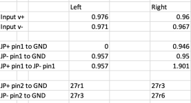
remove JP1+ and JP- shorties
conduct measurement with bal signal in:
JP+ pin1 to GND
JP- pin1 to GND
JP+ pin1 to JP- pin1
all that, to investigate buffers function ( expect same signal in - signal out)
while still powered ON, measure Rdc:
JP+ pin2 to GND
JP- pin2 to GND
all that, to investigate state of xformer windings
edit: in general - be sure that JP shorties are having proper contact; not once people had troubles because fo bad short there; you must feel proper resistance when pushing that thingie on pins
if in doubt - take new shorties, or squeeze contacts on existing ones
if still in doubt, just solder thin piece of wire between JP pins and be done
you have procedure for buffer setting explained in Build guide, I believe
re-check do you have suspicious buffer set to proper Iq and DC Offset
in fact - first thing to do - following already conducted procedure, you can check do you actually have signal reaching buffer input
that's "wiper" pad ...... trace it to buffer input , or point me to place where your ref. schematic is posted and I'll tell where exactly to put red probe
write here what you got
Hi guys,
I am trying to order parts I need for both the Zen Balanced Pre and the Pearl 3. I need the part number for the Schurter PEM for the balanced Zen Pre Modushop chassis. There are some part numbers in Post #3125, but I'm not sure if the SE chassis has the same opening.
Also, can someone explain to me 2 pole versus single pole for fuses? Is this caused by different safety rules in different countries? What should I be doing regarding this in the U.S.?
Thanks,
John
Last edited:
I seem to be in a perpetual state of confusion possibly due to jumping among three different projects......but for the balanced Zen Mod Pre V.4 SMD are we doing snubbers for the transformer? I saw a note from Patrick to leave them out at one point. Then the Zen Modest One redesigned the circuit and they were in. I just ordered the AN-0218 doughnuts. I'm confused and I don't even drink alcohol. I think I'm going blind looking at tiny part numbers.....But I did build the Quasimodo jig and the scope is ready to go. Snubbers or no snubbers, that is the question.
John
John
If the PCB has place for what appears to be 2 sets if snubbers, that’s the board that is ok.
If there’s only a place for one set of components, leave empty.
If there’s only a place for one set of components, leave empty.
They are the same.I'm not sure if the SE chassis has the same opening.
A quick internet search or two will reveal more (and be more accurate) than I can type in a minute or two. Here is one resultAlso, can someone explain to me 2 pole versus single pole for fuses?
For V4 SMD, you can install the snubbers, and they'll perform as intended.Snubbers or no snubbers, that is the question.
Maybe see if a drink clears the mind. (I'm kidding, of course.)I'm confused and I don't even drink alcohol.
I understand completely.I think I'm going blind looking at tiny part numbers
On a separate note. My apologies on my astrological predictions... the stars have not perfectly aligned, but Venus is in retrograde and things are looking promising. Kits will (highly likely) be ready for purchase end of next week.


which means, Patrick was/is extrabusybee
having available both Aleph Jzm and Iron Pre in Store ....... what's not to like?
Greedy Boy'z dream come true

I admit I was too ambitious in my estimated timing for measuring and binning the new batch of JFETs.which means, Patrick was/is extrabusybee
🙂 One of my absolute favorite combinations.having available both Aleph Jzm and Iron Pre in Store ....... what's not to like?
Greedy Boy'z dream come true
Yes, the V. 4 SMD Balanced pcb's each have two snubber locations, Rs, Cs, and Cx, and Rs*, Cs* and Cx*. I assume the asterisk is to differentiate the location of the two.If the PCB has place for what appears to be 2 sets if snubbers, that’s the board that is ok.
If there’s only a place for one set of components, leave empty.
Thanks Jim.
Thanks Patrick. It looks like you could use either a single pole or a double pole switch. In the U.S. double poles are usually used for high voltage devices (240V) as it's a safer way to disconnect from the mains when you bring in two 120V lines to an appliance.They are the same.
A quick internet search or two will reveal more (and be more accurate) than I can type in a minute or two. Here is one result
For V4 SMD, you can install the snubbers, and they'll perform as intended.
Maybe see if a drink clears the mind. (I'm kidding, of course.)
I understand completely.
Thanks for all the information.
John
Looks like this pre kit is soon to be available which is great as I just received the chassis from Gianluca!
The question is, will the kit cover everything else or I need to fish around for extra parts? I only have the chassis so far.
The question is, will the kit cover everything else or I need to fish around for extra parts? I only have the chassis so far.
- Home
- Amplifiers
- Pass Labs
- Iron Pre Essentials Kits For The DIYA Store - Register Your Interest

