Is this the place to ask remedial questions? Regrettably, I have a few.
1. What is the name of the gizmo in the attached picture? I'm thinking of something like this with a jumper to select between 6 and 12 db of gain, but my Mouser navigation abilities are weak. Yes, I can (and probably will) modify that thing I have, but I'd like to have the ability to order the parts I need.
2. How important (or not) is the snubber? I've stressed about it a bit as my transformer isn't listed in the Quasimodo Results. OTOH, I notice that several builds in the KISS thread don't have em.
3. I have a BOM indicating the lead spacing on C5 and C6 should be 10 or 15mm. It looks (to me, a noob) like it's either 5mm or 15mm. 10mm fits a couple of holes, but it doesn't seem like the right answer.
Thank you!
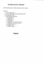
Note with thanks!All semiconductors accounted for, contents of two bags labeled 'A'.
I will note that the packing list shows LM336-5.0 while the schematic and the supplied parts are LM336-2.5.
Adjusted.
Is this the place to ask remedial questions? Regrettably, I have a few.
1. What is the name of the gizmo in the attached picture? I'm thinking of something like this with a jumper to select between 6 and 12 db of gain, but my Mouser navigation abilities are weak. Yes, I can (and probably will) modify that thing I have, but I'd like to have the ability to order the parts I need.
I call them headers / header strips. I use things like this and cut them to length. I have a zillion header caps from PCs etc., but you can order those too if you need them.
https://www.amazon.com/Straight-Bre...887792&sprefix=0.1+pitch,aps,3419&sr=8-3&th=1
I wouldn't sweat it. The good news is that several people building these will likely use the same Antek transformer and have Quasimodos to measure them. You can always add it later.2. How important (or not) is the snubber? I've stressed about it a bit as my transformer isn't listed in the Quasimodo Results. OTOH, I notice that several builds in the KISS thread don't have em.
I'm away, and I don't have the boards in front of me. If you've got your boards, you can just toss a ruler on them to confirm or someone may chime in with their confirmed measurement.3. I have a BOM indicating the lead spacing on C5 and C6 should be 10 or 15mm. It looks (to me, a noob) like it's either 5mm or 15mm. 10mm fits a couple of holes, but it doesn't seem like the right answer.
1. It’s called a header and has 2.54mm spacing. You can get them at Amazon as well as the mini jumper.
2. The Iron Pre will work just fine without snubber. Don’t jumper anything. I’m building mine without and installing later to see if there’s any objective/subjective difference.
2. The Iron Pre will work just fine without snubber. Don’t jumper anything. I’m building mine without and installing later to see if there’s any objective/subjective difference.
Good to know Patrick is at the help desk 24/7 with a quick response time and excellent customer service!!!
Last edited:

Here's the extent of my work this weekend...I don't have my Mouser order yet 🙁. Transformers and caps are just dry fit. The Silimic II's I was going to use are a tight fit...are they worth using in this position (C13-C20).


Couldn't find the actual Fujitsu relay at Mouser so I ordered these from Amazon:
https://a.co/d/9qTVQvV
Couldn't find the actual Fujitsu relay at Mouser so I ordered these from Amazon:
https://a.co/d/9qTVQvV
Last edited:
I spent some time today checking the parts list from the store; everything present and accounted for!
I do have the pieces to stuff most of it, so was sorting. I considered firing up the soldering iron and starting with resistors, but want to take some time to review the schematics and see how they translate to the board. I'm doing the balanced version and will ultimately have a mix of Balanced and SE "origins" and "All Outs"
@KevinHeem what are you using for the spade connectors I see at AC1, AC2 and all the inputs, and at the GND/V+/V- in the center of the board? I might want to duplicate that.
@Toadroller
ZM might not be happy with me using spades on his boards...but here's what I use anyway:
Spade: Mouser# 571-735427-2
Tab: Mouser# 571-174777-1-LP (I crimp and solder these).
I ran out and had to order more.
The GND/V+/V- in the center of the board are just some little test point loops.
ZM might not be happy with me using spades on his boards...but here's what I use anyway:
Spade: Mouser# 571-735427-2
Tab: Mouser# 571-174777-1-LP (I crimp and solder these).
I ran out and had to order more.
The GND/V+/V- in the center of the board are just some little test point loops.
Last edited:
as ZM is notorious to make a messssssssssssss - Quasimodo procedure - check what is appropriate arrangement for CT secondary
if one C+RC cell is adequate, proceed
if there must be C+RC cell between each secondary end and CT (so 2 cells), ignore ZM's ookoop with snubbbbber
in any case, inform me about your finding
disclaimer - with that low power and shunt reg isolation, there is hardly any need for snubbers
though, better sleep/OCD/whatever - all valid reasons for any overkill
Here's the extent of my work this weekend...I don't have my Mouser order yet 🙁. Transformers and caps are just dry fit. The Silimic II's I was going to use are a tight fit...are they worth using in this position (C13-C20).
View attachment 1169867View attachment 1169869
Couldn't find the actual Fujitsu relay at Mouser so I ordered these from Amazon:
https://a.co/d/9qTVQvV
use smaller caps
take care of using appropriate zener in relay voltage reg
27V for 24V relays
16V for 12V relays
any other - relay voltage+3 to 4V
Hi All -
Of note for those that have their kits already. I've gotten some wonderful feedback re: the BoM I posted earlier in the thread. Thank you, Kevin!
All parts SHOULD be listed, but I may have made a few errors with the notations in the spreadsheet against the schematic.
As always, double check against the schematic. I wanted to provide a BoM for everyone's ease, and I'll certainly update it when I get a moment to triple check it.
tl;dr - As always, check the schematic for final values and part identifiers against the silkscreen.
Thanks to all for the notes in the thread and via PM / e-mail. You're doing a huge service to those that will follow.
Cheers!
I've been staring at the schematics for a while now, which has prompted a question...what exactly is the purpose of T11 & T13 and T12 & T14 (+ surrounding components). Sorry to bring this down to a 101 level class.
Last edited:
always post link to your ref. schm, only way to avoid ookoops and confusion
then I'll reply properly
then I'll reply properly

Capacitance multiplier.
Edit: See first circuit here: https://www.electronics-notes.com/a...transistor/capacitance-multiplier-circuit.php
Edit: See first circuit here: https://www.electronics-notes.com/a...transistor/capacitance-multiplier-circuit.php
Hi All -
Re: Post #474
All posted BoMs from post #321 and schematics from #61 should be accurate. For those that may want a BoM to help out, please begin there.
If any errors are spotted or improvements recommended for clarity / ease of use, please let me know here in the forum or via PM.
Again, thanks to all the early builders for the great feedback. Keep it coming.
Best,
Patrick
Edited to correct post numbers for BoMs / Schematics.
- Home
- Amplifiers
- Pass Labs
- Iron Pre Essentials Kits For The DIYA Store - Register Your Interest