demons_wing said:what it T7 for in the first schematic?...only single ended input, but not current feedback...interesting...any idea how it works?
T7 must be the "turn on thump" blocker. T7 will conduct on startup and clamp the base of the output transistor, but as the capacitor charges, it turns off.
I'd say there's current feedback to the emitter of T3.
The gain of the initial T1/T2 stage is determined by R7 and R8.
Rune
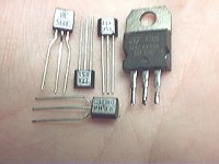
Yes Eva and friends. Those transistor strange.
This way, take a look at the simulator schematics, is use normal transistors, common audio units assembled inside as a switch darlington transistor. high Power Switch, may be HPS or the name Eva told us.
Do not tell anybody, but i am still using high power switch transistors in my two channels bass amplifiers.... and no big problem when hearing. But if i go to measure, i suppose i will se very strange waveforms there. This way i am not going to laboratory with those amplifiers i use for bas, i am only hearing.
Please Eva, may i know the simulator you are using?
regards all you, threaders and readers,
Carlos
runebivrin said:
I'd say there's current feedback to the emitter of T3.
Yes...you are right! This is current feedback!
By the way... lets make some business?
Eva, i will inform you the program i used to increase images, focus, ligths and effects.
And you inform me the program you used to simulate circuits.
Other thing i could see.... the hand that show us components show me a very complicated line related your life. this hand line show you faced heavy obstacles and not so easy to go on without beeing strong. (for free)
My program, used to image, and now i could read the number on the picture is ACDSee last one.
The amplifier, send us by Pjoltan, from Hungary, is rated from him as a 30 Watts amplifiers, this way he used probable 8 ohms and week voltage.
Estoy feliz, hay amigos en esto mondo.
Carlos
I use PSpice 6 schematics editor [win 3.11 version, pretty old but simple to use] and Orcad 9 pspice.exe to simulate and view results [since pspice.exe from PSpice 6 for win 3.11 doesn't work in win32 at all]
I also use EWB since it allows to quickly obtain bode plots for more ideal things like crossover networks or SMPS output filters
In the other hand, high power switching bipolar transistors tend to be fast and sometimes pretty linear but tend to show low current gains [10..50] and insufficient DC SOA margin for linear applications, altough <1uS pulsed SOA tends to be excelent [ie: I've seen TO-220 bipolar devices dissipating >1KW during 250ns at 2% duty cycle and still surviving, and even 5KW during 25ns]
Thank you Eva, and thank you all to help me
This is good, all you say i read and think about it, sometimes a take some notes about to not forget, sometimes i save it entirelly to read again and again.
Please, continue to make those analysis... go ahead please.
Carlos
This is good, all you say i read and think about it, sometimes a take some notes about to not forget, sometimes i save it entirelly to read again and again.
Please, continue to make those analysis... go ahead please.
Carlos
Ion pics
Hi!
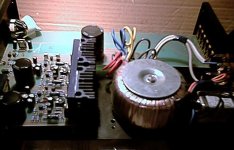
Here are some pics of my amp. Sorry for the bad quality, but my camera is not the best.
Lohk!
I wrote: "The schematic is a version of the Ion Obelisk." It was a kit version from Heed Audio. It is a hungarian company and the owner: Zsolt Huszti is the one of the most famous audio guru in my country. They was building the Ion Obelisk in the early 90's, and afther they made a KIT from it. You could share your shcematic to us to see what is different beetween them.
Destroyer X!
Nice work you did with the simulatins! Here is the time to build one for your self! It is easy and cheap and big fun. The sound will be very musical.
Greets:
Tyimo
Hi!
Here are some pics of my amp. Sorry for the bad quality, but my camera is not the best.
Lohk!
I wrote: "The schematic is a version of the Ion Obelisk." It was a kit version from Heed Audio. It is a hungarian company and the owner: Zsolt Huszti is the one of the most famous audio guru in my country. They was building the Ion Obelisk in the early 90's, and afther they made a KIT from it. You could share your shcematic to us to see what is different beetween them.
Destroyer X!
Nice work you did with the simulatins! Here is the time to build one for your self! It is easy and cheap and big fun. The sound will be very musical.
Greets:
Tyimo
Attachments
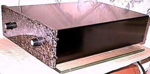

The way you made, using "eternal" material
This stone panel make me think, the enormous amount you trust in its musical qualities, because stone never ended, or, inside one house will never end. To be alive from now to ethernity, i think like a minimum it has a very good sound.
I will do it, i ensure you, but not now, there's a long strip to follow.
I am very interested in AKSA module, because the way hugh thinks, if some amplifier promisses to be good, i think this one can be... already paid, normal price, could not reduce a dollar, is on middle of the way.
Hugh and me, we have half world to travell, unfortunattely, because i think in met him someday, to have a beer together and take a lot of pictures aside this extraordinary man.
Also to see Rodd, i like him too, and if possible, the world most beatifull lady, the australian girl, Miss Universe 2004!
Congratulations you all Australian.
cheers,
Carlos
A few years ago somebody gave me a unit with this circuit configuration, I cannot tell if all the componants values were the same but the configuration was.
They gave the amp because it needed repair too often.
I remember that the amp did go in thermal ruaway often and blow output transistors I reduce the bias but heatsink were too small an there was no holes in chassi for ventilation.
The amp end up in parts in the junkbasket.
They gave the amp because it needed repair too often.
I remember that the amp did go in thermal ruaway often and blow output transistors I reduce the bias but heatsink were too small an there was no holes in chassi for ventilation.
The amp end up in parts in the junkbasket.
Congratulations to Carlos & Tyimo.
Excellent job done. U hv done all out to make the things success. But as Mr. Carlos said, he got 100W@4ohms, what about the output Tyimo u got? Both of u used the same modified circuit & pcb? Kindly give more details.
Mr. Carlos, how u find this compared to ur sony modified.
MP
Excellent job done. U hv done all out to make the things success. But as Mr. Carlos said, he got 100W@4ohms, what about the output Tyimo u got? Both of u used the same modified circuit & pcb? Kindly give more details.
Mr. Carlos, how u find this compared to ur sony modified.
MP
Thanks
Hi Carlos and Sajti : Thanks! and Köszi!
For me the Aleph5, JLH1969, Hiraga The Monster are the best amps until now.... Soon I will try the SOZ and the Zen LIght, but I like my Ion Clone's sound still.
Goranga Palesha! Thanks for you too! My amp work with 30-50mA bias and it gives with 30mA: 30W on 8 Ohm load and 50W on 4 Ohm load with 120VA transformer and 10.000uF capacitor.It is enough for me with my 90dB speakers.
Audiofan! Sorry for the bad experience. Off course higher bias mean biger heatsink....etc. My amp is working already 3 years long without any failure. 🙂)
Greetings for everybody!
Haribol!
Tyimo
I will answer gladly all of you, now running fast.
Latter i will put answer to all.
Welcome Mr. Roberto from Italy, he seem to be a beginner and he want to construct Mr . Polzac Zoltan amplifier.
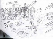
You want a schematic, this one is the schematic....i put as a paint image...if not clear, i can make one other better, you only need to ask... them i will do happy!
I need to know if you really a beginner or if you have some experience using boards.... as how to paint it, how to corrode it... do you use Ferric Percloret (Percloreto Ferrico) or what you use to corrode copper?
Do you like to assemble in the copper side or you like to make holes and solder the other side (more difficult, a little bit complicated)
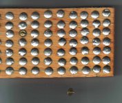
Do you like, as a beginner, to assemble first time in a wooden piece with cooper pins? the ones we use to fix advises in school.
They accept solder very well... and easy to see and solder and revise.... also big, enormous to see better... as a first, i recomend you to do this way.... can avoid frustrations!
But if you are skilled, i can do a board for you... i make them only seeing, make it fast... and delay to correct and check it.
You can see first scratch... and more informations about assembly in wooden base.
I love the picture of your town...magnificent place...just beautifull.
The transformer you have can hold exactly two channells... good..perfect.... exactly what you need.
No parlo benne italiano ma yo capisco molto bene.
Bienvenutto fratello d'italia Roberto, mi piace stare a tu disposizione.
You cominzziano la costruzione de la circuitazzione impressa.
ciau
regards,
Carlos (Carlos Danesi per voi)
Latter i will put answer to all.
Welcome Mr. Roberto from Italy, he seem to be a beginner and he want to construct Mr . Polzac Zoltan amplifier.
You want a schematic, this one is the schematic....i put as a paint image...if not clear, i can make one other better, you only need to ask... them i will do happy!
I need to know if you really a beginner or if you have some experience using boards.... as how to paint it, how to corrode it... do you use Ferric Percloret (Percloreto Ferrico) or what you use to corrode copper?
Do you like to assemble in the copper side or you like to make holes and solder the other side (more difficult, a little bit complicated)
Do you like, as a beginner, to assemble first time in a wooden piece with cooper pins? the ones we use to fix advises in school.
They accept solder very well... and easy to see and solder and revise.... also big, enormous to see better... as a first, i recomend you to do this way.... can avoid frustrations!
But if you are skilled, i can do a board for you... i make them only seeing, make it fast... and delay to correct and check it.
You can see first scratch... and more informations about assembly in wooden base.
I love the picture of your town...magnificent place...just beautifull.
The transformer you have can hold exactly two channells... good..perfect.... exactly what you need.
No parlo benne italiano ma yo capisco molto bene.
Bienvenutto fratello d'italia Roberto, mi piace stare a tu disposizione.
You cominzziano la costruzione de la circuitazzione impressa.
ciau
regards,
Carlos (Carlos Danesi per voi)
Attachments
- Status
- Not open for further replies.
- Home
- Amplifiers
- Solid State
- Ion Obelisk