https://www.diyaudio.com/community/...overs-without-measurement.189847/post-2834287Using an inductor with a series RC on a woofer is not necessarily a first order filter. In the plot below I've shown a fourth order slope on a woofer that I've used, and it is crossed using only those three components. The acoustic response is the goal, the electrical components are just the tools we use to get there.
Can you provide the attendant circuit diagram of the filter network that was referred to above? I can't seem to get my idealizations to work the way I expected.


Thanks for the circuit. I've set it up in VituixCAD as shown below.

The resulting filtered frequency response curve is shown below using the red line. As expected, at higher frequencies the roll-off rate is less than second-order, due to the impedance of the series RC leg becoming dominated by the resistor.
In addition, for comparison purposes, the blue line corresponds to the above circuit with resistor R1 short-circuited. In this instance, the response seems to be much more like a theoretical 2nd-order Butterworth filter response function, with a 12dB/octave roll-off rate.
Nonetheless, it gives the correct response for that speaker. I’ll go into a little detail about the process in determining this.
This was a 15” woofer crossed to a waveguide, so the cross is snug against the natural upper rolloff. I was using Speaker Workshop as a simulator which explains the unique looks and smoothing parameters.
I used full polar measurements to determine that I could cross on top of the relatively benign 1st breakup mode. This allowed me to get the “kick” I needed to flip to a steep crossover slope. The real reason for crossing there of course, was to match directivity.
The resistor isn’t a standard Zobel value, it was there to tune the damping of the knee of the rolloff and in this case it gave me the control I needed to get that right.
The baffle step happens below the room’s Schroeder frequency since the baffle is 60cm wide with the woofer occupying much of that. The response is therefore largely flat down to 200Hz, below which it gives a near textbook average step. (Somewhere I’ve posted a quasi anechoic shot of the averaged baffle response which is revealing.)
The upshot of this is that I virtually ignored the baffle step in the cross, and picked it up in the multi-sub implementation.
I am building a 2.5way tower using the Satori TW29DN-8 tweeter and two MW16-P midwoofers. Currently using the traced infinite baffle data for the drivers, which I loaded into both BoxSim and VituixCad. I found it easier to add the enclosure and model baffle step in Boxsim.
I just picked up an EMM6 measurement mic, but havent figured it out yet.
Here is my target for my first go at a crossover based on modeling from the traced data.
Other than that one 10mH inductor part, I have the rest of the components on hand to easily test.

One thing I am a bit concerned about is that plateau between 700hz-1200hz. How would I go about trying to flatten that part?
I just picked up an EMM6 measurement mic, but havent figured it out yet.
Here is my target for my first go at a crossover based on modeling from the traced data.
Other than that one 10mH inductor part, I have the rest of the components on hand to easily test.
One thing I am a bit concerned about is that plateau between 700hz-1200hz. How would I go about trying to flatten that part?
There are many ways to make such changes, it’s possible to get very fine control of response shape with passive components.
However it’s not always readily apparent how, and sometimes it can take a little work. I’ve given some examples in earlier posts of how the schematic can relate to the needed shape.
The first thing I’d do in this case is try tweaking each of the three existing components to see whether any has enough control over the problem region without affecting other areas too much.
The next thing I’d try is a bandstop filter. This is also known as a notch filter or band reject filter depending on where and how steep it is.
There are two main varieties to begin with. One involves a resistor, capacitor and inductor in parallel, the three inserted as an element in series with the existing inductor. Tweak the values as best you can.
If that isn’t satisfactory you can always try a resistor, capacitor and inductor in series, with that string placed in parallel with the driver.
Sometimes you can get greater control using two such filters together, with the frequencies side by side if that gives you the needed shape.
I'm curious why LPF 1.4khz, HPF 2.7khz are chosen so far apart (both second order, filter freq ~ 5khz/sqrt(mH*uF), evident from chart as well). Like AllenB said, L|C|R shelf-notch centered near 900hz (so mH*uF ~ 30, each value depends on impedance but product does not); followed by LPF closer to the HPF. Alternatively, just first order LPF 700hz (~160hz*imp/mH, for example 1.8mH for 8ohm impedance) and adjust HPF.
By the way first order HPF freq ~ 160khz/imp/uF.
By the way first order HPF freq ~ 160khz/imp/uF.
Last edited:
To my eye, the LPF and HPF acoustic responses appear to cross over at the same point, approximately 2.3kHz. Note that the responses look like they are about −5dB relative to the low-frequency and high-frequency passbands of the acoustic responses. This is indicative of the drivers being in-phase in the crossover region. With that type of design, one doesn't look for −3dB response points at the cross-over location, but rather the −6dB response points.
Thank you. I was wondering how to pick component values for a notch filter.i will try modeling that.Like AllenB said, L|C|R shelf-notch centered near 900hz (so mH*uF ~ 30
p.s. Notch filter is basically a first order crossover LPF/HPF applied to a single driver at two ends of the notch. Second order crossover is basically first order crossover LPF/HPF applied to each driver. So the math is the same.
Btw. I have a scarlet 2i2 audio interface and the Dayton EMM6 mic. I am going to download REW and try it out.
One question: when measuring the tweeter, I understand I can limit the freq sweep to 1000-20k Hz. I am still nervous about DC on the line and blowing it up. Can I place a 10uf cap in series with the tweeter as I measure? And is there a way to correct the response after?
One question: when measuring the tweeter, I understand I can limit the freq sweep to 1000-20k Hz. I am still nervous about DC on the line and blowing it up. Can I place a 10uf cap in series with the tweeter as I measure? And is there a way to correct the response after?
You probably don’t want to start the measurement as high as 1kHz, as phase will be in error.
There are three views towards including a capacitor in the measurement. Firstly, if you plan to use it permanently, use a smaller value to make it part of the filter and leave it in the circuit at all times. This way you don’t ever need to worry about how much affect it has.
Secondly if you want easy temporary use of a capacitor, then first mess around on a simulator and find a capacitance value that is large enough that it doesn’t have a significant effect at the frequencies you plan to use it.
Thirdly to do it more properly, choose any value you are comfortable with and use your simulator to create a curve of the difference with and without it. You can use this curve to add/ subtract with any other curve you measure.
You are fortunate to have Allen B supporting your effort.
I use the Scarlet when l need to verify network voltage drives. This is one way to verify your simulation is accurate with a real network with the real driver connected.
The thing is your acoustic measurements must be accurate. So must your impedance measurements. Always do tail correction and minimum phase transform before using them in a simulation for both impedance and FR measurements.
A 68 uF non polarised electrolytic won’t impact on the phase response but it will block any dc in the typical pass band of a tweeter.
REW is quite a versatile tool and is very well supported with help guides.
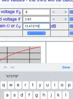
At 2.83 volts you won’t break anything. Measurements down to the resonance of your tweeter will be okay.
Sometimes in REW 2.83 volts will be too much and may overload REW. With a usb interface you should be able to reduce the input level to REW.
A reference voltage is not always practical
It might be only 0.5 volts.
This can be verified with the oscillator function in REW using a sine wave. Simply take an AC voltage measurement with your voltage meter at a known frequency.
To convert to 2.83 volts for your simulator use this online calculator
https://sengpielaudio.com/calculator-gainloss.htm
In REW you can add the magnitude difference in the calculator to normalise your FR measurement. Then export this normalised measurement to your simulation using the export function. Typically this is a text file ending in .txt
Obtaining the relative difference in FR spl is important because the levels in your simulation must equal when performing the crossover transformation.
This may require a resistance voltage divider if you are simulating a passive network.
Otherwise you won’t be able to determine the sum of the output of each driver at the crossover point.
I use the Scarlet when l need to verify network voltage drives. This is one way to verify your simulation is accurate with a real network with the real driver connected.
The thing is your acoustic measurements must be accurate. So must your impedance measurements. Always do tail correction and minimum phase transform before using them in a simulation for both impedance and FR measurements.
A 68 uF non polarised electrolytic won’t impact on the phase response but it will block any dc in the typical pass band of a tweeter.
REW is quite a versatile tool and is very well supported with help guides.
At 2.83 volts you won’t break anything. Measurements down to the resonance of your tweeter will be okay.
Sometimes in REW 2.83 volts will be too much and may overload REW. With a usb interface you should be able to reduce the input level to REW.
A reference voltage is not always practical
It might be only 0.5 volts.
This can be verified with the oscillator function in REW using a sine wave. Simply take an AC voltage measurement with your voltage meter at a known frequency.
To convert to 2.83 volts for your simulator use this online calculator
https://sengpielaudio.com/calculator-gainloss.htm
In REW you can add the magnitude difference in the calculator to normalise your FR measurement. Then export this normalised measurement to your simulation using the export function. Typically this is a text file ending in .txt
Obtaining the relative difference in FR spl is important because the levels in your simulation must equal when performing the crossover transformation.
This may require a resistance voltage divider if you are simulating a passive network.
Otherwise you won’t be able to determine the sum of the output of each driver at the crossover point.
Attachments
Last edited:
Edit: some changes were made to the above post after I made this post.
Minimum phase transform can be problematic on various fronts, and I wouldn’t use it without a specific reason.
Firstly, minimum phase transform will turn diffraction energy into a phase error. Diffracted energy is not intended to be taken as minimum phase and the response variation will be converted incorrectly.
Secondly, minimum phase transform will erase the measured delay and lose the wanted phase difference between drivers due to their natural time offset.
There are methods available for working out distance manually and these are intended for those times when a proper measurement system is not available, such as when USB mics are used.
Further, minimum phase transform cannot make up for tail errors, but Xsim can do an approximation for you.
Tail correction is a good idea, I agree. Preferably not too close to the passband as it is an approximation.Always do tail correction and minimum phase transform before using them in a simulation
Minimum phase transform can be problematic on various fronts, and I wouldn’t use it without a specific reason.
Firstly, minimum phase transform will turn diffraction energy into a phase error. Diffracted energy is not intended to be taken as minimum phase and the response variation will be converted incorrectly.
Secondly, minimum phase transform will erase the measured delay and lose the wanted phase difference between drivers due to their natural time offset.
There are methods available for working out distance manually and these are intended for those times when a proper measurement system is not available, such as when USB mics are used.
Further, minimum phase transform cannot make up for tail errors, but Xsim can do an approximation for you.
Last edited:
Sorry l am not 100% familiar with these simulators.
It depends on the overall approach.
My thinking was around obtaining the crossover transform for a passive network on a baffle as tutorial.
I use Linear X Leap 5 crossover shop over 15 years and it’s brutally accurate against direct measurement after a network is built. It always was and always will be.
There are two approach’s to measurement data as far as delay or distance is concerned. You’re using the alternative.
I measure the physical Z co ordinate from the baffle @ 1 metre. The distance from
the mic to the baffle is arbitrary but is input. The distance from baffle to the Z coordinate is what matters. This is why the minimum phase transformation is required.
If the driver is not a text book driver at the crossover point you need the minimum phase transformation for a passive network.
My apologies if l have disrupted your thread.
Thanks for your input.
One factor is that the acoustic centre varies with frequency even on a single driver. With no specific location to pin it on, a standard (non-minimum phase) measurement can show what’s happening, and there are no extra steps needed before crossing. To arrive at that you take both measurements (eg W and T) in timing lock. This is simple with Holmimpulse, and there are instructions readily available for rew and arta, as well as vituixcad measurement instructions.
Yes it is. Crossover response and phase calculations are generally accurate for calculations on paper or for crossover simulators old and new.I use Linear X Leap 5 crossover shop over 15 years and it’s brutally accurate
I’d argue that measuring delay to manage phase is a desirable way to do it.You’re using the alternative.
One factor is that the acoustic centre varies with frequency even on a single driver. With no specific location to pin it on, a standard (non-minimum phase) measurement can show what’s happening, and there are no extra steps needed before crossing. To arrive at that you take both measurements (eg W and T) in timing lock. This is simple with Holmimpulse, and there are instructions readily available for rew and arta, as well as vituixcad measurement instructions.
Last edited:
Wow. Amazing. Thank you all for the input and advice. I can process some of the advice, but still need to learn a lot before I really understand.
My plan so far is:
1) finish my 2nd speaker tower
2) set up the modeled crossover from Boxsim (externally, so I can tweak later)
3) listen
4) measure the whole speaker response with REW
5) then start with the individual driver measurements (unfortunately limited to in-basement measurement)
6) remodel in Boxsim and VituixCAD to further tweak the crossover
Also, I have a switch to choose between my Matantz receiver or my Tube amp. I generally use the receiver for movies and the tube amp for music.For the speaker impedance curve, it looks to range from 4ohms around 100hz up to 12 ohms at 2k and back to 8 ohms at 20k. Is this typically flat enough for an EL34 pushpull tube amp? Or should I invest further time in figuring out how to further flatten the impedance curve?
Does your tube amp have a 4 ohm transformer tape?
Otherwise depending on the output impedance of your tube amp this may impact on the tonal balance.
Otherwise depending on the output impedance of your tube amp this may impact on the tonal balance.
A push-pull amp probably has enough feedback to have a low output impedance already. Every one is unique.
Some might just use a single impedance circuit over the cross due to the typical 3k region being as sensitive as it is.
Regular EQ could do this as well, if that’s something you might happen to be doing for other reasons.
Some might just use a single impedance circuit over the cross due to the typical 3k region being as sensitive as it is.
Regular EQ could do this as well, if that’s something you might happen to be doing for other reasons.
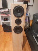
Well, back to the drawing board for this design. I had tried an MTM format, 15cm between tweeter and midwoofers, and 30cm between midwofer centers.I am building a 2.5way tower using the Satori TW29DN-8 tweeter and two MW16-P midwoofers
I was able to get a fairly smooth result. Sounded great on most stuff! But, the midrange just sounded smeared on complex passages, especially vocals. I guess it is from just too much driver overlap below the crossover, and possibly too much distance between the midwoofers in that critical midrange area.
I plan to switch to a 3 way design now. I am considering swapping out that lower Satori driver for an SB-17CRC (which I have in a 2 way bookshelf right now), perhaps even double up the woofer then.
Attachments
- Home
- Loudspeakers
- Multi-Way
- Introduction to designing crossovers without measurement