For the active high pass filter in a WAW build I would need to use very low value cap (47nf) to keep the filter input impedance low (10k).
Is there any disadvantage to such a small cap value, aside from the filter being more sensitive to the input impedance of following stage?
Is there any disadvantage to such a small cap value, aside from the filter being more sensitive to the input impedance of following stage?
Is the capacitor there to form a high pass filter with the 10k input to the amp? It will do so at around 300Hz. Do you have any further information?
10k is the high pass resistor, 300Hz is the intended XO point. The filter is on the input of an LM3886.
Ok, I understand you are trying not to get the filter mixed up with the existing input resistance.
Does your amp already have a coupling capacitor and a shunt resistor? It would be better to use them as part of this.
Does your amp already have a coupling capacitor and a shunt resistor? It would be better to use them as part of this.
The LM3886s will be part of it, the XO will be incorporated into them.
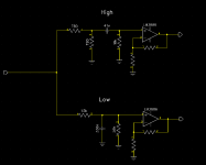
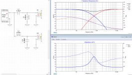
I attached schematic below of the whole thing for clarity.
I also wonder if the divider is necessary for the attenuator before the high pass or if a series resistor would do.
The ''preamp'' is a DAC with digital volume control,
I attached schematic below of the whole thing for clarity.
I also wonder if the divider is necessary for the attenuator before the high pass or if a series resistor would do.
The ''preamp'' is a DAC with digital volume control,
Attachments
Last edited:
I have used much smaller values in a different circuit without a problem.Is there any disadvantage to such a small cap value, aside from the filter being more sensitive to the input impedance of following stage?
Ok, thanks. Will probably go even lower then and use some spare foil polypropylene caps I have.
Hi Allen, would these crossover design principles work for a quick and dirty test crossover for a JMLC horn and compression driver? Thanks
Hi frangus. I'd add a couple of things in that case. The first is about finding the right crossover point. The second is about dealing with the tweeter impedance.
For a LeCleach horn, a couple of things.. it is typically better used above and not too close to its cutoff frequency... and it has a continuously varying directivity. Somewhere in there you'll find a directivity to match with a woofer. It will likely be around 90 degrees. This means the size of the woofer has to be chosen to match the cutoff frequency of the horn. hornresp.exe is good at predicting things here.
The impedance of a compression driver on a horn can be less simple than a dome tweeter. It can be sharper, higher and not a simple single bump. You can use the techniques shown in the tutorial but there will be more room for improvement in being more specific when fixing the impedance. With the right amount of work it should be possible to do it near perfectly.
what if we choose two different frequencies. for example for bass 2500hz, and for tweeter 5800hz. where in that case will the point of intersection be and what will the amplitude look like? The intention is to build a small 30w system. The crossover used would be a first order 6db. Should the polarity of the tweeter be reversed in that case? what would be the hole in the response in that case.
This is worth trying because first order is a special case. This is because the frequency that the first order formula gives, sets the response at -3dB. Typically, crossover responses are between -3dB and -6dB, often closer to -6dB.
This means you can experiment with a wider spread, and in your case each side is approximately half an octave from the cross. The filter responses will each be around -5dB where they intersect. Reverse polarity would be preferred in theory (*).
I wouldn't want to take them too far apart... In theory even though there appears to be a risk that they will add with a peak at the cross, the phase difference takes care of that and turns it into a potential advantage. Also, if you go too wide you'll get dips at the outer edges of the cross.
* All this theory depends on the drivers being flat to begin with, which they won't be.. so each case may vary.
When guessing at a crossover there are many things that can happen. Sometimes, you create one problem and it takes away another. Therefore it takes a little time to come to learn what makes sense and what doesn't.
Well the active crossover too didnt worked out. I have changed the tweeter to DC28F-8 and now the problem is gone. I am trying out a new crossover attached the screenshot from xsim, can you please have a look and suggest
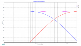
I like the way your response is up at around 200Hz, then it falls toward the treble and ends up around -6dB, in consideration of the baffle step.
I would suggest reversing the polarity of the tweeter, and if necessary relaxing the woofer near the cross.
I would suggest reversing the polarity of the tweeter, and if necessary relaxing the woofer near the cross.
I think the peak at crossover is the reason AllenB suggested relaxing the woofer near crossover if necessary. It is better to do that in order to preserve the good phase tracking through crossover that you now have
..
..
Let me try that, its very hard with series type of crossover when one component is.changed both tweeter and woofer gets changedI think the peak at crossover is the reason AllenB suggested relaxing the woofer near crossover if necessary. It is better to do that in order to preserve the good phase tracking through crossover that you now have
..
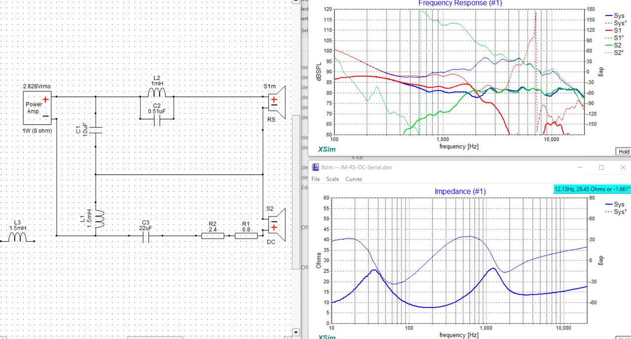
Hello all , i'm rookie in diy audio , and i did a project in Xsim 2way crossover , can someone give an idea about my project, if i did something wrong , i wanna build something good with less components , thank you
Attachments

Last edited:
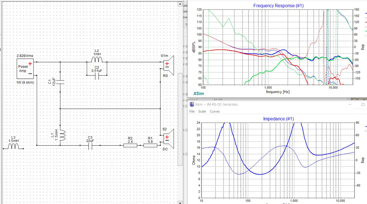
Something that all crossovers should be careful with is the combination of C3 and C1 as you've shown. Since you can draw a current path through them from one amplifier terminal to the other, a combination like that will represent a short circuit to the amp at some higher frequency. For this reason it drew my attention straight away.
The thing you need to do with Xsim is bring on individual plots, including separate driver response and phase, plus one total response. This two way example has five traces. Use the menu above the chart. The first time you do this it may seem fiddly but it reasonably straightforward.
Thirdly, what is the reason for L2/C4/R4?
Attachments
hello AllenB , thank you for your replay and advice also , i use those parts for impedance flattening , but i don't know if this circuit is necessary , on internet you can find a lot 2 way circuits crossover from 6db to 24 db and i don't know what to choose , my build project, in the beginning, i did what to use car speaker drivers , because of cheap drivers with crossover included , but from more deep research most speaker builders they not recommend them , because car speakers are build different that home drivers ( iam not worry about impedance that is low , my amp is also diy) , and again other confusion , what speaker to use ( i found some car drivers with very good price and very good frequency response like 39hz to 25khz ) , and home speakers also hard to choose , sorry that sounds that i am complaining , normal is easy to buy factory made speakers , but price is high and what you get is low quality , so i'm decide to build my own , buy some good drivers and build the right crossover for them. Project monitor speaker done by my hands 🙂
- Home
- Loudspeakers
- Multi-Way
- Introduction to designing crossovers without measurement