I imagine the required grid bias at 1.1kV is about -150V, with some adjustment range.
The bias regulator is adjustable, so if you use it you can remove the 10M45 [Q4] and K117 [Q3] connect to to the grid via the grid leak resistor, and set the bias regulator for -150V, nominal.
> Hi Rod, This is great news! I am also interested to order a couple of your new bias regulators. Please let us know when they are ready!
There will be some news soon!
Vincent states in his blog
"In this amp, the power tubes are biased at between -80 and -120 volts, depending on the tube type (graphite/copper)."
I looked for some GM70 datasheet for the different graphite/copper plates, but the two datasheets I found have equal specs... So it'd be interesting to figure out why do they require different bias voltage?
Perhaps the copper plate doesn't reach 125W dissipation?
Rod, I am going to send you a PM to file my order in.
If I'm sort of following this correctly, then it seems that your Bias boards are easy enough to drop in - along with your DHT Regulator boards - as well as the Raw DC Boards - though according to the original schematic it would require a slight retool of the Transformer for the DHT circuit, for which your boards would be a direct drop in. Am I missing something? Seems too good to be true but - with an increase in the secondaries to 8.8A min @ 20V - it seems like your boards drop in - then direct link up to the DHT regulator. Capacitance is somewhat different there.
Rod - your manual for the DC board recommends certain transformers etc - which I take to be one trafo per board (x2 for stereo pair?)
Additionally, it looks like Ale's SiC boards would be an easy drop in - and I'm going to dig into the mu-follower boards that he offers to see if those would be easy enough to drop in.
If it all checks out I think we may have well heeded all of Vincent's proposed changes/improvements.
Last edited:
Nice amps everyone!
<snip>
I went through my copper phase (3 sets) but these amps now do the bass in a 3 way active system so I use graphite plate.
Hi Michelag,
You misquoted me and I never saw your question until today.. LOL
I found the copper plate slightly cleaner and warmer in the midrange than the graphite plate, but it was not a big difference. The bass performance is better with the graphite plate probably due to lower rp when run at currents that are probably a bit high for the copper plate.
These days I only run graphite and I run them at reduced dissipation as compared to the past. (around 100W vs 125W) They last a few hundred hours longer before performance deteriorates.
I ran my first set of copper plate tubes at 125W and they survived to 1000 hours, subsequent pairs ran at 100W.
The last set of graphite plate ran an estimated 1500hrs - a record for me. (More than 30 hrs a week for 11 months)
I'm on my 12th set of output tubes and due to problems managing the heat during the warmer months of the year I am contemplating a new amp design around the EML520B which should give about the same power output with less than half the power consumption. These amps have been in service for 11 years now.
Thank you @kevinkr Kevin for your contribution. Do you note a need to change grid bias for the two plates?
@Vincent77 do you happen to have your car files for drilling and engraving the top plate? I was buying the enclosures and perhaps let hifi2000 do that job...
Thanks!
@Vincent77 do you happen to have your car files for drilling and engraving the top plate? I was buying the enclosures and perhaps let hifi2000 do that job...
Thanks!
I run them at different grid bias, but I just have a bias pot I adjust while monitoring the plate current.
The first pair ran fine at the maximum rated current, but that current level isn't necessary with 7K primary Z that I am using and I actually got slightly more output power at the lower current because my IT coupled D3A driver is not able to deliver significant grid current and this slightly increased the maximum available grid voltage swing before the driver stage ran out of headroom due to increasing grid current in the GM70.
The first pair ran fine at the maximum rated current, but that current level isn't necessary with 7K primary Z that I am using and I actually got slightly more output power at the lower current because my IT coupled D3A driver is not able to deliver significant grid current and this slightly increased the maximum available grid voltage swing before the driver stage ran out of headroom due to increasing grid current in the GM70.
@Vincent77 do you happen to have your car files for drilling and engraving the top plate? I was buying the enclosures and perhaps let hifi2000 do that job...
I have the file, but it's in proprietary format of Schaeffer CAD. I can send it to you if you want.
Yes please!I have the file, but it's in proprietary format of Schaeffer CAD. I can send it to you if you want.
Thank you infinitely!
Michelag: if you are using Rod's bias regulator, it would make sense to reduce the interstage capacitor C3 from 0.47µ to 0.22µ and increase the resistor R11 from 100K to 220K.
Yes, thanks for the hint, i guess I will reproject the bias pu with a voltage doubler instead of your tripler, so I can get the 110/140 vdc needed...Michelag: if you are using Rod's bias regulator, it would make sense to reduce the interstage capacitor C3 from 0.47µ to 0.22µ and increase the resistor R11 from 100K to 220K.
So i guess with same bias voltage i won't need the changes you suggested?
I used a voltage tripler only because I wanted to use a transformer I already had in stock, so yes, use a normal rectified or a voltage doubler if you want.
The changes to C3/R11 are to use a smaller/cheaper capacitor. Some people say that smaller capacity coupling caps sound better.
The changes to C3/R11 are to use a smaller/cheaper capacitor. Some people say that smaller capacity coupling caps sound better.
The change to 220K and 220nF coupling cap works perfectly with my bias regulator. The anode-current monitoring (via Vincent's Arduino design) is a relief from any worries about runaway current with a big hot tube.
If a range of bias voltages 100-140V is right for the operating point at 1100V, a standard catalogue transformer 55V or 60V rms can be used with the voltage-doubler kit. A very low cost 56V 100mA rms trafo (example: Mouser Part No 530-241-4-56 ) will give about 160V DC, and higher-current 55V versions, or a 60V part, will give a little more.
If a range of bias voltages 100-140V is right for the operating point at 1100V, a standard catalogue transformer 55V or 60V rms can be used with the voltage-doubler kit. A very low cost 56V 100mA rms trafo (example: Mouser Part No 530-241-4-56 ) will give about 160V DC, and higher-current 55V versions, or a 60V part, will give a little more.
Their function is to act as a low pass filter (coupling cap+ grid leak resistor) , so this modification would apply in general, not only for the changed bias supply, right?Michelag: if you are using Rod's bias regulator, it would make sense to reduce the interstage capacitor C3 from 0.47µ to 0.22µ and increase the resistor R11 from 100K to 220K.
And by the way, what's the bias you were using for graphite/copper plates?
And by the way, [emoji14] on the hifi2000 case, did you drill yourself the sides to suit as heatsinks?
Last edited:
Right.
I don't remember exactly the bias voltage, but I noticed important differences between graphite and copper plate tubes.
I drilled the HiFi2000 heatsinks, it's fairly easy.
I don't remember exactly the bias voltage, but I noticed important differences between graphite and copper plate tubes.
I drilled the HiFi2000 heatsinks, it's fairly easy.
I built this amp in 2014-2015... wow, time flies.
Things I would improve today:
- biasing the driver tubes with series SiC Schottky diodes like C3D02060F
- try replacing the CCS driver anode loads with Ale Moglia's hybrid mu-follower circuits for lower output impedance (higher circuit complexity, though)
- the CCS biasing circuit sounds great. BUT it's not the most stable: it depends on the circuit's temperature. It stabilizes after 10 minutes or so, but I would try using Rod Coleman's shunt fixed bias regulators instead.
- in the B+2 power supply, one could use a better/more modern CCS for the voltage reference
1) just make a series of those two Schottky's and done... stuck on the 3.4V (they have a Vf of 1.7V if I remember well)
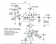
2) I read the articles, here calculating component values for 8-10mA current is not so easy... (pic attached for 240V HT, 130V anodic, 2P29L tube), though it becomes very very interesting for its lower load impedance... have to put a little brain in that
3) done, wait for Rod 😀
4) Yes, one could, but why bother when we have a working scheme? 😀
Attachments
Last edited:
Additionally, it looks like Ale's SiC boards would be an easy drop in - and I'm going to dig into the mu-follower boards that he offers to see if those would be easy enough to drop in.
If it all checks out I think we may have well heeded all of Vincent's proposed changes/improvements.
Hi cmv260, any news on that front? This gyrator caught my eye, but I guess some components values need to be adapted...
Is Ale Moglia on diyaudio ?
Let's invite him to join the discussion! 😀😀😀
though according to the original schematic it would require a slight retool of the Transformer for the DHT circuit, for which your boards would be a direct drop in. Am I missing something? Seems too good to be true but - with an increase in the secondaries to 8.8A min @ 20V - it seems like your boards drop in - then direct link up to the DHT regulator. Capacitance is somewhat different there.
Rod - your manual for the DC board recommends certain transformers etc - which I take to be one trafo per board (x2 for stereo pair?)
If it all checks out I think we may have well heeded all of Vincent's proposed changes/improvements.
sorry to step in between you and Rod, but it could become misleading for other users...
for DHT, just use the given schematic. 20VAC 8A (160VA) double secondary transformer, and at the end Rod's DHT regs. (see figure)
I would like to add a picture of the modfied bias power supply (the voltage doubler with a 55-60V transformer, but since this has been done by Rod, I don't like to hurt his business... (except he gives me permission) so just ask him.
I would like to summarize and schematize all the modification we want to introduce to the scheme, for future reference.
Thanks.
Yes, you can use Ale's Anode-load for the driver, and at the same time, use the Source-follower board he offers, to drive the GM-70 grid.
Using a DC-coupled follower gives excellent control of the grid over wide swings, and as further temptation, it allows the coupling capacitor (which will now be from the µ-follower's output, to the source follower's input) to drop in value to 47-68nF - because it can face a resistor of (example) 510kΩ for the SF input.
Source Follower PCB – Bartola(R) Valves
1) just make a series of those two Schottky's and done... stuck on the 3.4V (they have a Vf of 1.7V if I remember well)
Yes, but if you use C3D02060F, it's better to increase current in the driver tubes to 13-14mA, because their If-Vf characteristics are more linear at higher current. Vf is around 0.85V at this current,
so two diodes will indeed bias the driver at -1.7V.
- Home
- Amplifiers
- Tubes / Valves
- Interesting GM70 scheme... Some questions on the PSU, who helps me please?