I was looking to have the transformers wound by the folks at Audiophonics in Bordeaux - anyone have experience with them?
Actually I ordered the toroids directly from one of Audiophonics' suppliers (at least one I heard they were using back then) - Petra Toroid
I have also been very satisfied with these power transformers: ESO Transformateurs They can wind per your specs.
Last edited:
Hi!
The relays are SPST, mains rated, contacts for at least 3A, coils for 6 volts.
I programmed the Arduino. The firmware is attached below.
Excuse me again, it is the first time I use such relays...
Are they all three equal? Or there are different relays, one that's only time delay, and other ones specifically built as inrush/surge limiter?
These three are commanded by the Arduino, or the relays shown in the Arduino schematic are different?
I just can't figure out how can the Arduino control and switch the relays...
Yet is the temperature sensor that small thing at the left of the Arduino board?
Had a look at mouser website... Well there are too many relays 🙁
The relays' coils are commanded by the Arduino controller through the ULN driver. When the software commands an output port to go high, the specific relay coil gets powered by 6 volts and it closes the switch.
So, relays are rated by:
- the voltage needed by the coil - here you need 6 volts.
- the current needed by the coil: the lower the better. Maximum 500mA is supported by the driver.
- the contact type: we need a SPST NO contact (single pole, normally open)
- the contact voltage rating: at least 230vAC (or your local mains voltage).
- the contact current rating: how much current it can switch without damaging the contacts. Here I would say 3A is a minimum - 10A would be better.
In this schematic, all three relays are he same kind.
One is used to delay turning on B+ until the driver tubes are hot.
The other two reduce the inrush current in the big toroidal transformers. They are optional, and not needed if you use EI transformers.
The temperature sensors are also optional. I think I used LM335Z, 3-pin TO-92 sensors. They are connected with long wires to the controller's inputs. I put the sensors under the transformers, to check their temperature and cut the power if they get too hot (but this never happened so far).
.
The temperature sensors are also optional. I think I used LM335Z, 3-pin TO-92 sensors. They are connected with long wires to the controller's inputs. I put the sensors under the transformers, to check their temperature and cut the power if they get too hot (but this never happened so far).
And now everything is crystal clear!
I'll filter out some relays at mouser to match those specs.
But what's this? (See picture)
Thank you a lot... It's like completing a puzzle 🙂

yet still if the arduino cuts off the power, won't the current pass through the termistors paralleled with the relays?
some more questions, as coupling caps did you use 2x FT-3 0.22uF or just one k-40Y with 0.47 uF ?
output transformer, in a previous forum message you stated that
"The Lundahl LL1688 sounds very good, but the high frequency square waves on the scope show that it has some
resonances. Because of this, I would probably choose another transformer for a new GM-70 project."
however better to keep output impedance 10k-ish or would you go some lower?
I was thinking for this (my final) project to use iso tango transformers, and let it be my last heritage work (for the moment 😀 )
thanks,
Michelangelo
Ok, for those interested, i created a BOM at Mouser's,
accessible under this link:
Access to this page has been denied.
It misses the big caps to be paralleled to reach 100uF/1200V
it misses the 2uF 1200V PIO russian, to be found on epay
it misses the 0.47uF coupling caps, of your choice,
2SK117GR has been substituted with 2SK209-Y, although thinking of Rod Coleman's shunt fixed bias regulator is an alternative.
It misses of course tubes, tube sockets, power and output transformers, and the Coleman DHT regulators.
Please let me know if you an access it when needed.
Last edited:
yet still if the arduino cuts off the power, won't the current pass through the termistors paralleled with the relays?
some more questions, as coupling caps did you use 2x FT-3 0.22uF or just one k-40Y with 0.47 uF ?
output transformer, in a previous forum message you stated that
"The Lundahl LL1688 sounds very good, but the high frequency square waves on the scope show that it has some
resonances. Because of this, I would probably choose another transformer for a new GM-70 project."
however better to keep output impedance 10k-ish or would you go some lower?
I was thinking for this (my final) project to use iso tango transformers, and let it be my last heritage work (for the moment 😀 )
thanks,
Michelangelo
The power is cut by the delay relay (named "tempo" in the schematic), not the inrush ones. Only B+ is cut, not the heaters.
I used indeed 2x FT-3 0.22uF; K-40y PIO are warm and musical, but to my ears they lack surgical precision and details.
Lundahl transformers are good. But today I would probably choose a nice amorphous 6K1 transformer from Monolith .
Michel,
Thank you for sharing BOM - here is an option for the cap in a single can:
mouser 598-944U101K122ACI
Vincent had mentioned Wima options - there is a 1100V @100uf
505-DCP5-100/1100/10
or perhaps two of these - 871-B32373A4207J080
Thank you for sharing BOM - here is an option for the cap in a single can:
mouser 598-944U101K122ACI
Vincent had mentioned Wima options - there is a 1100V @100uf
505-DCP5-100/1100/10
or perhaps two of these - 871-B32373A4207J080
I will personally parallel 4 of these per channel:Michel,
Thank you for sharing BOM - here is an option for the cap in a single can:
mouser 598-944U101K122ACI
Vincent had mentioned Wima options - there is a 1100V @100uf
505-DCP5-100/1100/10
or perhaps two of these - 871-B32373A4207J080
MKP1848625924Y2
Good call -
Did you have a spin at retooling the Bias PSU and circuit for the Coleman Regulator? I will give it some work tonight.
Did you have a spin at retooling the Bias PSU and circuit for the Coleman Regulator? I will give it some work tonight.
Good call -
Did you have a spin at retooling the Bias PSU and circuit for the Coleman Regulator? I will give it some work tonight.
Well,not yet... I wanted to leave a message to Rod, since can't find any buying option for the bias reg on his website...
For the dht reg yes, perhaps he didn't commercialize the bias reg?
If you want to give it a go you're welcome, so we split a little work 🙂
I'll write tomorrow an email to three winders for the 3 power trasformers, one in italy, one in Romania and one in Poland, let you know when they give me a quote, if you are on the same part of the pond...
Big question point for the TU though...
Good call - let me know if Rod replies, no use in spending too much time if he's no longer offering the boards.
I wanted to order the Regulator boards/kit soonish anyways. Then save up a little cash for those Monolith OPTs!
In the states, but frankly havent had too much luck here, need to spend more time quoting the toroidals locally.
If the Bias Reg does work out, may call for a change in the secondaries on the 80/8 toroidal - or otherwise work it out in the circuit.
Thanks again for the BOM, I was in the same process, but not I can compare some of our choices! 😉
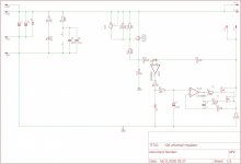
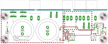
Heres a design for the heater regulators for GM70
Ive designed this to heat GM70's and 833's for that matter. its completely configurable with two resistor swaps.
I want to add a optocoupler to a new version, to interface these regulators with digital control logic, in that way you can shut down the amplifiers should either the regulators fail internally or the heater breaks.
If anyone wants to try some, i have boards available at cost.
Telegram support group for the regulator can be found on the DIYAUDIO landing page on :
Telegram: Join Group Chat
Another possibility is the use of a AC optocoupler like the LTV-814 and a 555 to provide a high signal as long as the 6.3V is present.
This is very helpfull when you want to do floating measurements on the heater voltages. HCNR200
Attachments
Last edited:
> Good call - let me know if Rod replies, no use in spending too much time if he's no longer offering the boards.
I wanted to order the Regulator boards/kit soonish anyways.
The negative bias regulators will be available again shortly - I'm re-laying them out after designing (and shipping) a positive regulator for a special project. this regulator gives a performance that is a big step forward from the original bias regulator. Please send some email or PM if you'd like updates on it.
The new positive version has DC drift in the millivolt region, and much lower noise than IC regulators: for example <50µV rms for 76V, and is almost 100 times better than ICs at the same voltage (IC regulators typically render 40-50µV per volt of output in rms noise). A true negative regulator (a simple complementary version of this new design) gives the best noise rejection for bias supplies.
> I wanted to leave a message to Rod
There's an email address on the "Rod Coleman Regulator" homepage, or you can send me some diyAudio PM.
Rod Coleman DHT Filament Regulator
The Filament Regulator - as used in Vincent's GM70 design (as discussed in this thread) - is still offered there.
Hi Rod,
This is great news! I am also interested to order a couple of your new bias regulators. Please let us know when they are ready!
This is great news! I am also interested to order a couple of your new bias regulators. Please let us know when they are ready!
but in the end what is GM70 grid bias voltage?
the DC supply is at -250V, what sees the grid effectively?
I'm discussing this with Rod, about purchasing his raw DC supply + negative bias regulators
the DC supply is at -250V, what sees the grid effectively?
I'm discussing this with Rod, about purchasing his raw DC supply + negative bias regulators
Michelag: Yes, and it's your fault for dragging me back into this! 🙂 I want to make a 45 SE, I have some nice NOS tubes that have been sleeping for 80 years...
- Home
- Amplifiers
- Tubes / Valves
- Interesting GM70 scheme... Some questions on the PSU, who helps me please?