many sources.
Interested in writing an article(s) for Jan ? I'd like to understand this better : )
Thanks !
.
Last edited:
Interested in writing an article(s) for Jan ? I'd like to know more : )
Thanks !
.
I've already asked him about the process. I am not sure what topic to consider. And my life is about to become very hectic I fear.... 9 cargo containers worth of wire to install (so far).
And you are welcome..
John
Perhaps, problems would be lessened if the amplifier is built with an AC outlet for source/preamp.
.
.
I've already asked him about the process. I am not sure what topic to consider. And my life is about to become very hectic I fear.... 9 cargo containers worth of wire to install (so far).
And you are welcome..
John
I'll take it! 😉
jan didden
I've already asked him about the process. I am not sure what topic to consider. And my life is about to become very hectic I fear.... 9 cargo containers worth of wire to install (so far).
And you are welcome..
John
JN
After all this discussion are we really talking insulated or uninsulated wire, maybe you mean cable?
9 containers! Ah, Mid size jobs are the best! Efficiency of scale is nice. On large jobs the travel times kill you. Worst is when you start on the 7th floor north and have to get to the 9th floor south and there is no east or west. Down 12 flights of stairs (Some floors are 2x high) around the service level track and then up 15 flights. (Elevators are either turned off so they don't get scuffed or haven't been installed yet.)
One of these days I am going to have pictures taken of my crew before and after. Should be able to sell it as a diet plan on late night TV.
If you ain't havin fun... delegate!
Best of luck.
ES
Oh, picky picky..😀JN
After all this discussion are we really talking insulated or uninsulated wire, maybe you mean cable?
535 mcm DLO cable down to 1/4 inch microwave cable.
9 containers! Ah, Mid size jobs are the best! Efficiency of scale is nice. On large jobs the travel times kill you. Worst is when you start on the 7th floor north and have to get to the 9th floor south and there is no east or west. Down 12 flights of stairs (Some floors are 2x high) around the service level track and then up 15 flights. (Elevators are either turned off so they don't get scuffed or haven't been installed yet.)
Two floors, so not that bad. 4.5 kilometers of cable tray, thank goodness it's not conduit. Well, most of it anyway.. I think I like my job better than yours..sheesh.
One of these days I am going to have pictures taken of my crew before and after. Should be able to sell it as a diet plan on late night TV.
I wish I could lose weight that easily.
I'm too old to pull that stuff..If you ain't havin fun... delegate!
Best of luck.
ES
And, thanks..
Cheers, John
Perhaps, problems would be lessened if the amplifier is built with an AC outlet for source/preamp.
.
Yes, I agree.. But convince the high end guys to do that...😱
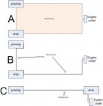
Here's something I put together in dec 2008.
A is the normal setup. edit: it is extremely susceptible to externals, as well as haversine.
B is what happens if you arrange the power of the source to strafe the amp, and you wrap the IC's around the preamp cord. Note that you've removed virtually all the loop area. edit: the loop would be capable of trapping external flux. Note that there is still the preamp ground to amp loop formed that will still couple to the amp haversines.
C is the closest to what you said. edit: It minimizes the coupling from the amp draw to the ground loop. Your suggestion goes one step better than this diagram. as an additional note, this is the setup I used to run 125 foot unbalanced lines from a balcony to a stage.
Cheers, John
Attachments
Last edited:
Oh, picky picky..😀
535 mcm DLO cable down to 1/4 inch microwave cable.
JN
Pickier still.
DLO is insulated wire, or just wire as you can slide on the insulated part as that is normally assumed for electrical purposes.
Should we talk about effective skin depth of 535 mcm wire and why that size?
It's talking Tesla Time!
ES
It is not the responsibility of the IC to decide which path the return current is supposed to take. It's purpose in life is to get the signal to the amp.
It is the function of the system to prevent intrusion of error, and exclude any errors that make it past the front end blocks..
The primary issue is how to keep external signals from getting into the input along with the music. Twisted pairs, coax, balanced are all techniques designed to reduce intrusion. However, implementation of them always has compromises.
I posted pictures showing:
1. How signals get into the ground and signal loops via induction.
2. How signals get in vs frequency by modelling the IC/safety ground.
2. How signals in the ground couple to the low level circuitry.
3. One method for shunting the ground current in such a way that the star reference path the input uses does not see either current IR drop, or dI/dt based induced voltages on the reference ground. This method uses a very little known fact that a cylindrical sheet of current does not generate an internal magnetic field.
The real issue with IC's is not the IC..it's the system. Until the real problems with the system are understood, characterized, and designed around this, all single ended systems may react differently to different IC's.
Bottom line, there is no way to determine what IC will match what system. No way to determine IF there could be a difference. No way to determine what to look for to make a specific change..
It is not possible to answer your question in the way you wish. Sorry.
Cheers, John
You`re mixing in internal issues here to more or less explain why IC`s won`t do their job as intended. You`ve got some point`s, signal-layouts is definetly a important case but I do not agree in using it as an excuse for sub-optimal IC`s not delivering.
As I`ve mentioned; I`ve found and used a non-audible IC that has shown to work in all kind of equipment I`ve tryed it on through the decades, and that includes quite a bit that I`ve made up for folks & friends.
Despite of signal-layouts, this IC opens up and dissapears leaving the systems performance exposed. So it can be done.
You`re mixing in internal issues here to more or less explain why IC`s won`t do their job as intended. You`ve got some point`s, signal-layouts is definetly a important case but I do not agree in using it as an excuse for sub-optimal IC`s not delivering.
I've not used the system as an excuse. What I've pointed out is that there are elements of the system which are not considered by the designers, and it is those considerations which cause the system to be sensitive to the IC's.
It is not "sub optimal" IC design. It is the overall system. In addition, I have also layed the groundwork which show that the LINE CORD does indeed couple to the ground loop and affect it's role on return currents. Both by ground connection resistance, and by cord geometry.edit: Once it is understood that the line cord can indeed couple to the ground loop, several messy things pop their ugly head...haversine spectra is impacted by the diode reverse recovery speed, main supply storage capacitance, capacitor ESR, internal AC line layout, main supply wiring layout...man, it gets ugly. That is why I pointed out odd harmonics in the primary loop, even harmonics in the secondaries...so that others could measure and attribute.
As I`ve mentioned; I`ve found and used a non-audible IC that has shown to work in all kind of equipment I`ve tryed it on through the decades, and that includes quite a bit that I`ve made up for folks & friends.
Despite of signal-layouts, this IC opens up and dissapears leaving the systems performance exposed. So it can be done.
I have not argued that modification of the IC is useless, nor have I made any claims whatsoever that changing IC's is NON audible. On the contrary, I have provided a clear explanation as to WHY an IC can cause system differences that may or may not be audible. But certainly measureable.
So do NOT confuse what I have done with that of the title of this thread. I have simply pointed out that standard system design is non rigorous, and that the variability in what an IC can or cannot do is a direct result of much very very bad engineering.
Bad engineering being defined as the lack of EMC considerations in most audio equipment. Note that I'm confident some designers do it right.
Cheers, John
Last edited:
JN
Pickier still.
DLO is insulated wire, or just wire as you can slide on the insulated part as that is normally assumed for electrical purposes.
Well I certainly hope so...we'll hipot to 5Kv.
Should we talk about effective skin depth of 535 mcm wire and why that size?
Exponential approximation or bessels?
It's far simpler however.. 440 amps DC, tray rated 90C in a 1600 meter long series loop.
Uh oh, the audio world equivalent of Ben Grimm...😀It's talking Tesla Time!
ES
Cheers, John
I am not sure what topic to consider.
Bruno took the F word, but you could corner the market on the H word. What is a haversine, and why should I care ? Polish what you know and the diagrams you've already made. Submit it to be included with Scott's part two !
.
Last edited:
Well I certainly hope so...we'll hipot to 5Kv.
Exponential approximation or bessels?
It's far simpler however.. 440 amps DC, tray rated 90C in a 1600 meter long series loop.
Uh oh, the audio world equivalent of Ben Grimm...😀
Cheers, John
JN
440 amps? Is that all you've got? I hope it is at least at 1KV or more!
4850 feet in tray on one floor! Did I ever mention the guy who stood on the end of the cable tugger when the cable broke? None of the survivors will make that mistake again.
Bessels of course with slide rules at dawn!
I should mention one arena I worked on where it had to be fed from 2 substations, as neither had enough capacity left to do it solo.
The initial design had a ring of ground rods driven around the arena and one substation tied in at the north point and the second at the east point. I explained this would produce a potential gradient everywhere in the building. The method I proposed had both feeds tie their neutrals together and then go to the grounding system. The PE in charge of the design understood the need for the extra and rather costly cable and issued the changes required. The electrical contractor looked at the scheme and did not understand the extra cable and came back with "I can save you some money..." The good news was my RFI (Fancy term for memo) was clear enough and well circulated so the answer was "No do it the way it is shown."
ES
JN
440 amps? Is that all you've got? I hope it is at least at 1KV or more!
1200V. Current stability at less than 10 PPM.
4850 feet in tray on one floor! Did I ever mention the guy who stood on the end of the cable tugger when the cable broke? None of the survivors will make that mistake again.
Like I said, I like my job better than yours..
Bessels of course with slide rules at dawn!
Hmmm..the force is strong in this one...darn, no darth vader smileys...
Cheers, John
1200V. Current stability at less than 10 PPM.
Like I said, I like my job better than yours..
Hmmm..the force is strong in this one...darn, no darth vader smileys...
Cheers, John
Picky time again "stability at less than 10 PPM" I presume you mean "better"
Wake me up if you get to even a single MW!
Last edited:
Picky time again "stability at less than 10 PPM" I presume you mean "better"
You know, you're worse than Steve Eddy...🙂
All 900 supplies will total more, but only one needs 535kcmil.Wake me up if you get to even a single MW!
The rf is 5mW, but their output "cable" is a tad larger...6 by 18 inch rectangular, and hollow...Gonnabe a BI to pull...😛
Cheers, John
Bruno took the F word, but you could corner the market on the H word. What is a haversine, and why should I care ? Polish what you know and the diagrams you've already made. Submit it to be included with Scott's part two !
.
While you ask a rhetorical question, others may not know the definition. Googling finds navigation stuff, so I include a link to a paper.
A description of haversine current draw is on page 4, with fig 6 on page 5 showing what it is on the bridge side of the transformer.
http://www.newark.com/pdfs/techarticles/fairchild/s Power Switch _FPS_ Components.pdf
Cheers, John
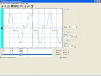
Openings, openings... Haversine = 1/2 Sin Squared of (x/2)
Attached is a real picture of the current draw... not a haversin!
Attachments
While you ask a rhetorical question, others may not know the definition. Googling finds navigation stuff, so I include a link to a paper.
A description of haversine current draw is on page 4, with fig 6 on page 5 showing what it is on the bridge side of the transformer.
http://www.newark.com/pdfs/techarticles/fairchild/s Power Switch _FPS_ Components.pdf
Cheers, John
... almost looks the same in Real World.
jan
Attachments
Openings, openings... Haversine = 1/2 Sin Squared of (x/2)
Attached is a real picture of the current draw... not a haversin!
That's all I could find, dude...take it up with the author..
What you posted is the primary side of the transformer, what shows up at the line cord. The paper I linked to was full bridge on ac line, I described the depiction as that on the bridge side of the xfmr...
What the heck is that spike, leakage inductance?
Hey, have a great weekend..I'm outta here...
Cheers, John
- Status
- Not open for further replies.
- Home
- Design & Build
- Parts
- Interconnect cables! Lies and myths!