Here are 4 separate derivations, none of which mention the word infinite.
http://www.math.ubc.ca/~feldman/apps/telegrph.pdf
Telegrapher's Equations
Transmission lines
This one is particularly good, it has both time and frequency domains...
The Telegrapher's Equation
w
Thanks for the links.
If you examine the transmission line link , the third one, you see that it is an idealized set of equations, with no regard to R or G.
It is however, exactly what I used for my model. And, as such, does not contain elements R or G, which in theory would slow the response down even more.
The discussion in that link is on reflections is geared more towards frequencies where standing waves develop.. As I previously said, anything in audio is generally DC to any lengths we discuss here.
So, my analysis essentially is about how the cable fills up with energy inconsistent with it's characteristic impedance simply because the load defines the "long term" V and I. I modelled reflections to provide the fill, consistent with Shadowitz.
I'll look at the others later, but that title was the most interesting.
edit: The last one was really great for historical reference. Note that he discusses calculations using an HP48...whoa.
No joy with respect to the current discussion...but a nice read.
Again, thanks.
Cheers, John
Last edited:
If you examine the transmission line link , the third one, you see that it is an idealized set of equations, with no regard to R or G.
What do you think, I don't read the material I quote? Perhaps that is the standard you have grown accustomed to in your other correspondents, but please make room for the possibility that I may be different. Try and understand how you might feel if somebody made that selfsame remark, 'If you examine the transmission line link' to you in the circumstances in which you made it to me. Of course I've read the link.
Again, thanks.
You're welcome. Stop talking down to me and we'll get on fine.
w
If you include R the line becomes slower at audio frequencies. Alternatively, you get a little attenuation at RF or pulse frequencies which will speed up settling by reducing the reflected waves from each end. In conditions of severe mismatch this attenuation may be significant. If you are reflecting 99%, then an extra 0.1% lost through line attenution will reduce your settling time by 10%.
Question: if you are bouncing pulses, what attenuation do you use, as this will be frequency dependent (e.g. via skin effect)? You need to be careful that you are not mixing different assumptions in the same model.
Given that the settling time is much smaller than 1/bandwidth I would be very surprised if it is noticeable.
If you include R the line becomes slower at audio frequencies. Alternatively, you get a little attenuation at RF or pulse frequencies which will speed up settling by reducing the reflected waves from each end. In conditions of severe mismatch this attenuation may be significant. If you are reflecting 99%, then an extra 0.1% lost through line attenution will reduce your settling time by 10%.
Agreed. Now, what ramifications for audio?
On the assumption that Jim Brown's graphs were done correctly, I haven't checked them....
At 1Khz, he shows prop velocity as 30e6, vs the hf asymptote of 200e6, a factor of 7 slower.
At 1 Khz, he shows Zo as 700 vs 75 at hf, a factor of 10 higher.
If I drop velocity a factor of 7, the 50:1 now becomes 42 microseconds settling.
If I increase Zo a factor of 10, zip goes to 1000 ohms, raising the ratio to 500:1 at 2 ohms, 125:1 at 8...maybe 200 to 500 uSec now?? (WAG)
Since I'd drive a step in less than a nano, I've forced the final voltage at hf Z, I won't see the effects of lf changes. Anything I calc using this method will only be fastest possible. Same with anything measured, it will be best case. I do not even believe nano rises will survive a zip cord, between stranding and pvc.
I'd have to go sine, and look for prop delay and settling in the load current. I gotta tell ya, looking for 10's of uSec timeshifts in current going into a 1 to 10 ohm load is not an easy task. The CVR will have to be amazing.
No skinning for now. I need to crawl first, not even walk. And, mixing assumptions? Yes, certainly a worry.Question: if you are bouncing pulses, what attenuation do you use, as this will be frequency dependent (e.g. via skin effect)? You need to be careful that you are not mixing different assumptions in the same model.
While neither rigorous nor mature, peer review and brainstorming via the web/forums is still early on the learning curve. Discussions with people who are not CPC's is extremely valuable, as it provides extreme cross-discipline communication that does not happen much.
Given that the settling time is much smaller than 1/bandwidth I would be very surprised if it is noticeable.
Settling time smaller than inverted bandwidth? You are a master of understatement.
When I initially found research (courtesy of Jon Risch) which detailed 1.5 uSec levels of discernment interaural, I was astounded. My initial reaction was the exact same as yours.
Cheers, John
ps. CPC....cut n paste clown..one who pretends to understand via google. We all know them.
Your spikes bouncing back and forth are, to a first approximation, not affected by R or G (because they are high frequency). The LF model clearly is affected by R and G (Z0, propagation speed). The two models must give almost the same answer, as they are both applications of EM theory; one used sines, the other uses impulses but these must be equivalent. This suggests that the actual outcome is not affected by R and G: HF because C and L dominate, LF because line shortness dominates. Yet the simple CR cable model clearly does include R (different R - this one is Rxlength). So does the line resistance matter or not? For an interconnect, line R will be swamped by output impedance of the driver which will not be too far off the line impedance so the line will be back-terminated (at least approximately). I assume your model is not driving the line with a pure voltage source?
Sorry, a bit rambling, but I am thinking out loud.
Sorry, a bit rambling, but I am thinking out loud.
There`s a lot of theoretic cable experts around, including all cable manufacurers, diy`ers a.s.o.. They`ve all got one thing in common; they can`t come up with a non-audible, "invisible" IC. But talk to them about cable-theori and they`ll convince you.
Years back in my speakerbuilding-days I stumbeled over this cheap IC-solution that showed to be absolutely open, uncolored & non-audible. The funny thig is that most audiopholes refuces to accept such a cheap & simple solution, the prefer theyr silver-gold or whatever exotic overpriced snakes they`re using.
Years back in my speakerbuilding-days I stumbeled over this cheap IC-solution that showed to be absolutely open, uncolored & non-audible. The funny thig is that most audiopholes refuces to accept such a cheap & simple solution, the prefer theyr silver-gold or whatever exotic overpriced snakes they`re using.
Your spikes bouncing back and forth are, to a first approximation, not affected by R or G (because they are high frequency). The LF model clearly is affected by R and G (Z0, propagation speed). The two models must give almost the same answer, as they are both applications of EM theory; one used sines, the other uses impulses but these must be equivalent.
I've wrestled with that a while.
The pulse I put in has to be of sufficient width to last longer than the settling. I assume 50 uSec to be sufficient for now.
A mercury wetted reed, I can run at a 120 hz rate. The actual test will be leading edge only, as a mechanical duty cycle is not going to cut it for trailing edge jitter reasons. I'll trigger rising edge level based.
While a 1khz repetitive pulse has an equivalent fourier, the settling time will be independent of the duty cycle or rep rate, it will be dependent only on the bouncing/settling of the leading edge with plateau and how the line/load settled. So the lower frequencies cannot have any effect, as there will be no distinction between a 50 usec pulse width and a simple step that remains high forever.
This suggests that the actual outcome is not affected by R and G: HF because C and L dominate, LF because line shortness dominates. Yet the simple CR cable model clearly does include R (different R - this one is Rxlength). So does the line resistance matter or not? For an interconnect, line R will be swamped by output impedance of the driver which will not be too far off the line impedance so the line will be back-terminated (at least approximately). I assume your model is not driving the line with a pure voltage source?
I also assume it is R and G independent, but primarily because I've used a step.
I'll do zip cable first, low load. My model is pure voltage, zero output impedance. In reality, audio hardware cannot do this at the speeds I'll drive, but I'm trying to remove the foibles of the output stage from the result. I could try my SWTPC 250 tiger in later trials, but while it can rise to 40 volts in 10 uSec, the servo loop causes droop. I worry about changing that given the signal and load nature.
The reed switch will be covered by braid, the output current will be through the reed, the return through the braid. The cap bank will be comprised of multiple lytics (I believe), each axial lead and low esr, with return current flowing through braid covers I slide them into. The coaxial scheme reduces the external inductance of each capacitor and zero's the internal and external inductance of the capacitor returns (the braid has no internal inductance, it's external is cancelled by the core current of the cap).. All caps will connect to the reed at one point in space, same with the all the braids. The maximum number of caps I can use will be limited to the spherical volume surrounding the nodes.
Sorry, a bit rambling, but I am thinking out loud.
Duly noted and appreciated...welcome to the club...😉
Cheers, John
There`s a lot of theoretic cable experts around, including all cable manufacurers, diy`ers a.s.o.. They`ve all got one thing in common; they can`t come up with a non-audible, "invisible" IC. But talk to them about cable-theori and they`ll convince you.
Years back in my speakerbuilding-days I stumbeled over this cheap IC-solution that showed to be absolutely open, uncolored & non-audible. The funny thig is that most audiopholes refuces to accept such a cheap & simple solution, the prefer theyr silver-gold or whatever exotic overpriced snakes they`re using.
Yah, I've noticed that as well.
IC's are particularly troublesome because the return current is not controlled. Balanced systems don't control for pin 1 currents very well through the audio band. It's a mess.
If only all the manufacturers in the world took a really good EMC course.
Cheers, John
This means that your results will not tell us much about audio interconnects when used in real-life situations. The finite driving impedance of, say, a preamp output will damp down transients by absorbing some of the reflections. This will reduce settling time, perhaps considerably.jneutron said:My model is pure voltage, zero output impedance. In reality, audio hardware cannot do this at the speeds I'll drive, but I'm trying to remove the foibles of the output stage from the result.
Bear in mind that if you drive zip cable too fast you will start to get losses from radiation.
Well, are you going to share it with us or keep it to yourself?PaleRider said:I stumbeled over this cheap IC-solution that showed to be absolutely open, uncolored & non-audible.
Balanced systems don't control for pin 1 currents very well through the audio band. It's a mess.
What pin 1 currents? Pin 1 is to connect the shield to ground (usually only at one end ). The small amount of EMF noise current is almost always RF.
Another observation: Are you using the HF model to try to explain LF effects? (line length << wavelength) You know that for infinite lenghts the LF (audio) impedance is very high (infinite at DC). How can you reconcile this with short audio interconnects?
If you know the impulse response of a circuit then you can, in principle, calculate the response to almost any other signal. However, you have to be careful as a big LF effect might be the cumulative result of lots of tiny HF effects which may be accidentally ignored.
This means that your results will not tell us much about audio interconnects when used in real-life situations. The finite driving impedance of, say, a preamp output will damp down transients by absorbing some of the reflections. This will reduce settling time, perhaps considerably.
Agreed. That is why I'm driving zip into an ohm or two. Power output stuff first.
For pre outs, it may be that a specific output z would need to be figured. I am of the opinion that it currently has no standardization, but I may be incorrect.
That is why I said a nano rise may not even make it. I'd also keep it away from metals just because of the dipole magnetic field. I chose 250 ps rise with mercury wetted relays only because it is trivially easy...I cut my teeth on a tek 109 back in the 80's.Bear in mind that if you drive zip cable too fast you will start to get losses from radiation.
What pin 1 currents? Pin 1 is to connect the shield to ground (usually only at one end ). The small amount of EMF noise current is almost always RF.
Check out Bill Whitlocks stuff on pin 1 currents. He uses a transformer, and resistor to drive 60 hz current into pin one to determine sensitivity to the current.
The test does not address the possibility of higher frequency coupling. If there are any mutual couplings between the pin 1 to safety ground path, and either the input signal, ground, or even feedback loop after the gain divider, it will show as proportional to frequency. 60 hz may not be enough.
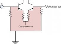
I have attached a depiction of the area which I believe is the most susceptible to induction within the chassis..as well as the ground connection shown to the ground of the input. The pink area is where any trapped rate-of-change flux would create a voltage, and this location is the area of highest gain.
Star grounding can also do this, and there are ways around it, the second pic shows how to remove the coupling from the input ground connection for a single ended circuit. Note that the shield that carries the noise current must be cylindrical...a cylinder of current does not produce internal magnetic field, so the green wire will be untouched.. The circuit must also be away from the noise current as well however.
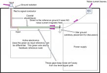
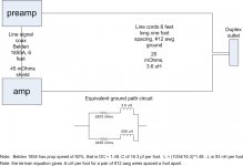
I also included a model of the groung current return path for a single IC connecting an amp to a source. This determines the breakpoints for the current path, which in turn determines the loop susceptibility to external flux. At very high frequencies, it all goes through the IC shield.
Odd, the pdf just sits there...oh well..
The pdf shows the system loop that actually traps flux, and how it couples into the circuit. Two things on that are missing (I believe) from current thinking: 1, the internal mag coupling of the amp, and 2, the same at the preamp. I do not believe many consider the source as possibly the origion of hum or noise, but it certainly can be. As far as I know, the pin 1 test is not applied to any outputs, just inputs..
If you know the impulse response of a circuit then you can, in principle, calculate the response to almost any other signal. However, you have to be careful as a big LF effect might be the cumulative result of lots of tiny HF effects which may be accidentally ignored.
I'm not too sure how to consider this in the grey area between simple lumped sum and t-line propagation. My guess is, discussion of any test results will be long and full of different opinions.
Such is life.
Cheers, John
Attachments
Last edited:
Another observation: 1Are you using the HF model to try to explain LF effects? (line length << wavelength) You know that for infinite lenghts the LF (audio) impedance is very high (infinite at DC). 2How can you reconcile this with short audio interconnects?
1. Yes, the hf model. We've discussed that at length here.
2. By sticking my head in the sand of course...🙂
Seriously, one of the primary reasons for this approach is to consider the total inductive and capacitive energy storage of the interconnect or speaker run. When the system has settled down to a final value (which given the wavelength, is all the time), the cable will not have the current/voltage relationship of it's characteristic impedance, but that of the load. By allowing the reflections to come and go until they die off, it is possible to view how the cable is filling up with energy. For a speaker, the current rises in the load and in the cable for every pass of the reflection until it asymptotically approaches the final load driven level.
Cheers, John
Yah, I've noticed that as well.
IC's are particularly troublesome because the return current is not controlled. Balanced systems don't control for pin 1 currents very well through the audio band. It's a mess.
If only all the manufacturers in the world took a really good EMC course.
Cheers, John
Hmm, so you think the case with IC`s is to control the retur-current? If that`s the case, can you come up with a non-audible IC to back up your statement?
I`ve enjoyed my diy non-audible IC`s for quite some years now, return-current or not. They`ve shown to be just as superb in booth balanced & single versions.
Can i ask, if the IC isn't controlling (or attempting to) the return current, what is!
One of the first rules of EMC is minimise current loops.
Is this lack of control of return current in the audio bandwith due to DC return following path of least resistance, then as the frequency rises it moves toward following the path of least inductance?
One of the first rules of EMC is minimise current loops.
Is this lack of control of return current in the audio bandwith due to DC return following path of least resistance, then as the frequency rises it moves toward following the path of least inductance?
Hmm, so you think the case with IC`s is to control the retur-current? If that`s the case, can you come up with a non-audible IC to back up your statement?
It is not the responsibility of the IC to decide which path the return current is supposed to take. It's purpose in life is to get the signal to the amp.
It is the function of the system to prevent intrusion of error, and exclude any errors that make it past the front end blocks..
The primary issue is how to keep external signals from getting into the input along with the music. Twisted pairs, coax, balanced are all techniques designed to reduce intrusion. However, implementation of them always has compromises.
I posted pictures showing:
1. How signals get into the ground and signal loops via induction.
2. How signals get in vs frequency by modelling the IC/safety ground.
2. How signals in the ground couple to the low level circuitry.
3. One method for shunting the ground current in such a way that the star reference path the input uses does not see either current IR drop, or dI/dt based induced voltages on the reference ground. This method uses a very little known fact that a cylindrical sheet of current does not generate an internal magnetic field.
The real issue with IC's is not the IC..it's the system. Until the real problems with the system are understood, characterized, and designed around this, all single ended systems may react differently to different IC's.
Bottom line, there is no way to determine what IC will match what system. No way to determine IF there could be a difference. No way to determine what to look for to make a specific change..
It is not possible to answer your question in the way you wish. Sorry.
Cheers, John
Can i ask, 1if the IC isn't controlling (or attempting to) the return current, what is!
2One of the first rules of EMC is minimise current loops.3Is this lack of control of return current in the audio bandwith due to DC return following path of least resistance, then as the frequency rises it moves toward following the path of least inductance?
1. The return current will follow the path of least reactance. The electrical model I provided is a rudimentary description using approximate numbers. It was put up to show that there are multiple paths of varying elements.
2. Absolutely accurate. As the depiction shows, normal single ended systems do not do that.
3. EXACTLY. Well stated.
It must be pointed out that given the resistances shown in my model, small things like safety ground line cord contact resistance, RCA shell contact resistance, IC shield guage can all have a non-trivial impact on the current paths through the audio spectrum.
The return path current is forming multiple loops at various frequencies. Each loop will have some frequency response based on the element forced breakpoints.
Get rid of the loops, or live with the fact that the system will be dependent on really silly things like 10 or 20 milliohm contact resistance changes in the IC's or line cords..
Cheers, John
"The ground loop current depicted in red is formed by the trapped magnetic flux within the grey loop."
above quote from the pdf
What generates the magnetic flux ? The leakage currents ?
.
above quote from the pdf
What generates the magnetic flux ? The leakage currents ?
.
many sources.
1. Single bushing utility feed transformers on the telephone pole split neutral current between the house shared neutral wire and the earth via a grounding electrode every other or third pole. (Cali had two bushing IIRC). Mike Holt figured about 5% of the domestic neutral current travels via the earth. This current is under and around all residences, creating field. edit: This is in great part, why the cable feed to the house can cause hum headaches...it is seeing the neutral line earth current that is travelling from the xfmr common on the pole to the house internal ground connection, that being either the service entrance earthing rod, or the plumbing bond, or some combination of both.
2. Romex created a dipole field which falls off as 1/R... If two romexes are stapled one on another, and one is part of a ground loop formed by plugging various system components in different outlets, half of the other's field will couple to the ground loop. If the agressor load is inductive and uses a contactor, the dI/dt can be HUGE, so even if coupling is weak, well we've all heard those pops..Old dimmers didn't have dI/dt spec limits either.
3. The equipment itself pulling power from the wall.. Power amps generally pull a haversine current from the line. While the ground of a line cord may be immune to it's co-habitors current by geometry, the rest of the ground loop is NOT immune. This can cause some components of the haversine be coupled into the ground loop. The nefarious part is, it's worse when the equipment is at it's loudest, so it can be masked. No intrusion when quiet does not necessarily mean all is well.
4. Within the equipment.. Is the internal wiring/xfmr designed such that it's own operation doesn't generate a flux which, combined with an external wire loop, causes a system ground current..
Note that haversine currents are all odd order. Currents after the bridge are even order with audio as well. It's all modulated by the power delivered to the load.
Cheers, John
Last edited:
- Status
- Not open for further replies.
- Home
- Design & Build
- Parts
- Interconnect cables! Lies and myths!