Windings on the same core do not shunt each other when in parallel. If you have 2 1H windings and you put them in parallel, you still have a 1H inductor because they are on the same core. So it's not so much how LTspice treats inductors as it is their physical operation. This confused me once too.
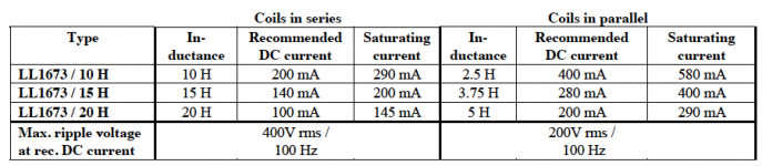
I'm not a hundred percent sure I'm following you and my language might be making the issue ambiguous. Attached are the numbers for 3 different gappings of Lundahl 1673. In series the winding inductances add and in parallel they divide.
Looking at this and following the instructions as Mooly posted (set the value of each coil first and then add the directive linking the two together on the same core) is LTspice doing the division or leaving the effective L at the nominal value.
Attachments
Turn the resistor around and it will be correct... honestly. So is the resistor directional 😀
Don't even begin to ask me to explain it because I don't know the answer. I believe itis to do with the fact LT needs reference 'direction' inbuilt into the resistor.
Maybe someone has an easy to read explanation but I agree it sure is confusing.
Don't even begin to ask me to explain it because I don't know the answer. I believe itis to do with the fact LT needs reference 'direction' inbuilt into the resistor.
Maybe someone has an easy to read explanation but I agree it sure is confusing.
Yup, confusing. I found this:
LTspice confusing resistor current reference direction | Electronics Forum (Circuits, Projects and Microcontrollers).
LTspice confusing resistor current reference direction | Electronics Forum (Circuits, Projects and Microcontrollers).
LTspice must keep track of the connections on the resistor so it labels internally one end '1' and the other end '2' (or similar). All sims do this.
Apparently the LTspice internal convention is that current runs from pin 1 to pin 2. So swapping the connections reverses the current. I agree is isn't very elegant ...
Jan
Apparently the LTspice internal convention is that current runs from pin 1 to pin 2. So swapping the connections reverses the current. I agree is isn't very elegant ...
Jan
LTSPICE's predecessors removed this ambiguity by removing the ability to print or plot the current in resistors, capacitors, diodes, inductors, and transistors. The only thing it would print or plot is the current in an independent voltage source. And, since a voltage source unambiguously has a polarity, the reference direction for its current is also unambiguous.
You want to plot the current in R3? Install a zero volt voltage source in series with R3 and plot the current in that voltage source.
In the LTSPICE world, nothing prevents you from creating your very own schematic symbol of a resistor. You can intentionally mark on the symbol, the reference direction of current. Either with an explicit arrow, or with some sort of asymmetry in the drawing. To borrow a good idea from KiCad PCB, you can use a rectangular box with leadwire stubs. BUT one of the four corners of the box, has got a diagonal slash across it. That end of the box is "pin 1" of the resistor, and current flowing INTO pin 1 is a positive number of milliamps. Current flowing OUT OF pin 1 is a negative number of milliamps.
_
Attachments
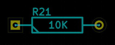
i did wonder why the arrows were pointing in the wrong direction, i thought i had done something wrong.Turn the resistor around and it will be correct... honestly. So is the resistor directional 😀
Don't even begin to ask me to explain it because I don't know the answer. I believe itis to do with the fact LT needs reference 'direction' inbuilt into the resistor.
Maybe someone has an easy to read explanation but I agree it sure is confusing.
i did wonder why the arrows were pointing in the wrong direction, i thought i had done something wrong.
My 2 cents (but I am not 100% sure about this [only 99.999%])
Look it this here
https://www.diyaudio.com/forums/sof...ltxvii-beginner-advanced-281.html#post6677038
The resistor is actually a current source/sink and it has/shows that same arrow.
Close then 😀 Thanks. I can see what has happened... your link has a page number embedded into it which depends on your own personal settings. If you right click the post number and copy the link it doesn't add the page number, only the post.
Guys, does anyone know which diode parameter controls the forward bias voltage for an LED?
I need to select an LED for a specific bias but it is not clear (for me) what the forward voltage is for a specific diode, otherwise I could fudge it.
For instance:
.model NSSW008CT-P1 D(Is=.23f Rs=17.6 N=3.43 Cjo=42p Xti=120 Iave=35m Vpk=5 mfg=Nichia type=LED)
What determines the forward voltage?
Edit: I need one with about 1.7V at 1 or 2 mA.
Jan
Last edited:
Maybe this helps SPICE diode parameter table
In retrospect: I'm sorry this is not what you where looking for 🙁
But still it may help someone 🙂
Here are some hits
Light Emitting Diode Specifications: LED Characteristics >> Electronics Notes
In retrospect: I'm sorry this is not what you where looking for 🙁
But still it may help someone 🙂
Here are some hits
Light Emitting Diode Specifications: LED Characteristics >> Electronics Notes
Last edited:
Hi Frans, yes I thought it would be a specific parameter, but it appears there's more involved modelling the actual curve when the diode opens up.
In the mean time I found a model from Cree that gives me a nice 1.68V at 1.6mA.
.MODEL XPEB_RDRDOAMB D ; red LED 1.68V @ 1.6mA
+ IS=6.7935e-016
+ N=2.2823
+ RS=0.57268
+ XTI=15.38565
+ IKF=0
+ EG=2.1000
Jan
In the mean time I found a model from Cree that gives me a nice 1.68V at 1.6mA.
.MODEL XPEB_RDRDOAMB D ; red LED 1.68V @ 1.6mA
+ IS=6.7935e-016
+ N=2.2823
+ RS=0.57268
+ XTI=15.38565
+ IKF=0
+ EG=2.1000
Jan
It's time to dive into the LTSPICE Wiki and find the obscure section which talks about the dark art of .STEPping the model name.
Now just .STEP through three dozen LEDs and pick four of them whose simulated VF meets your need best. Then buy ten pieces of each of the four part numbers and measure all forty. Which one has a mean VF closest to 1.7V? Which one has the tightest standard deviation? Which one can you actually buy in a global supply constrained environment?
If you want to look at model parameters, start with IS, N, and RS. They work together as shown in post #38 of the thread about Walt Jung's GLED431. Attachment #4 to that post suggests that maybe, just maybe, the effect of RS is very small at 1mA. If this happens to be true for every LED that you consider, then you can copy out the IS and N values, put em in an Excel table, and calculate Idiode from a 2-parameter model
Idiode = IS * exp( Vdiode * (1/N) * (q/kT) )
where kT/q = 25.8 mV and so (q/kT) = 38.76 V-1
(Invert the expression to get Vdiode = f(Idiode, N, IS) and then put in Idiode = 1mA. Presto, Bob's your uncle.)
Remembering the whole time, of course, that SPICE models are sometimes accurate and sometimes inaccurate. There are wild variations, depending on the expertise of the technician who did the actual work, and also the accuracy of every person who copy-and-pasted the parameters, in a long human chain from (model originator) to (you). Executive Summary: Vfwd in SPICE may not be Vfwd in real life. Especially when you include manufacturing variations a/k/a standard deviation.
_
Last edited:
That is a cool post Mr. Jung's ultra-low noise VREF - the GLED431
It also shows that this site needs tags (e.g. tagging) probably user maintained and then it needs to be posible to browse the site by these tags. Many good knowledge for scattered subjects is hidden in all kinds of subjects and can not be reached as it is currently working. Maybe there is some one reading this with the cloud to do something in this area. I just wanted to vent this idea 🙂
It also shows that this site needs tags (e.g. tagging) probably user maintained and then it needs to be posible to browse the site by these tags. Many good knowledge for scattered subjects is hidden in all kinds of subjects and can not be reached as it is currently working. Maybe there is some one reading this with the cloud to do something in this area. I just wanted to vent this idea 🙂
It's time to dive into the LTSPICE Wiki and find the obscure section which talks about the dark art of .STEPping the model name.
Now just .STEP through three dozen LEDs and pick four of them whose simulated VF meets your need best. Then buy ten pieces of each of the four part numbers and measure all forty. Which one has a mean VF closest to 1.7V? Which one has the tightest standard deviation? Which one can you actually buy in a global supply constrained environment?
If you want to look at model parameters, start with IS, N, and RS. They work together as shown in post #38 of the thread about Walt Jung's GLED431. Attachment #4 to that post suggests that maybe, just maybe, the effect of RS is very small at 1mA. If this happens to be true for every LED that you consider, then you can copy out the IS and N values, put em in an Excel table, and calculate Idiode from a 2-parameter model
Idiode = IS * exp( Vdiode * (1/N) * (q/kT) )
where kT/q = 25.8 mV and so (q/kT) = 38.76 V-1
(Invert the expression to get Vdiode = f(Idiode, N, IS) and then put in Idiode = 1mA. Presto, Bob's your uncle.)
Remembering the whole time, of course, that SPICE models are sometimes accurate and sometimes inaccurate. There are wild variations, depending on the expertise of the technician who did the actual work, and also the accuracy of every person who copy-and-pasted the parameters, in a long human chain from (model originator) to (you). Executive Summary: Vfwd in SPICE may not be Vfwd in real life. Especially when you include manufacturing variations a/k/a standard deviation.
_
You're a star Mark, thank you very much!
In fact I do have LEDs with the wanted Vf but I was struggling to find a corresponding spice model.
Excellent tip on stepping model names - in hindsight ...
Jan
Last edited:
Hi everyone! I have a spice question that I have a hard time to answer. I am trying to use a Matched BJT, namely the BCM61B. Nexperia provides a spice model, which confuses me a little. Mainly this passage:
.SUBCKT BCM61B 1 2 3
Q1 1 2 3 MAIN 0.9005
RQ 1 11 870.5
Q2 11 2 3 MAIN 0.0995
D1 2 1 DIODE
(whole .model statement can be found below)
If I interprete that right, then the whole two transistor circuit that makes up the matched current mirror is already fitted in a three Pin model/Circuit. If so, how do I place it correctly? Do I have to make a new symbol?
Thanks for the Help in Advance!
**********************************************************
*
* BCM61B
*
* Nexperia
*
* Matched double NPN/NPN Transistor
* IC = 100 mA
* VCEO = 45 V
* hFE = 200 - 450 @ 5V/2mA
*
*
*
*
* Package pinning does not match Spice model pinning.
* Package: SOT 143
*
* Package Pin 1: Collector;Base TR;TR1,TR2
* Package Pin 2: Collector TR1
* Package Pin 3;4: Emitter TR1;TR2
*
*
* Extraction date (week/year): 14/2020 (TR1) / 14/2020 (TR2)
* Spicemodel includes temperature dependency
*
**********************************************************
*#
* Please note: The following model is to be used twice in
* schematic due to equality of both Transistors.
*
*
* Diode D1, Transistor Q2 and resistor RQ
* are dedicated to improve modeling of quasi
* saturation area and reverse mode operation
* and do not reflect physical devices.
*
.SUBCKT BCM61B 1 2 3
Q1 1 2 3 MAIN 0.9005
RQ 1 11 870.5
Q2 11 2 3 MAIN 0.0995
D1 2 1 DIODE
*
.MODEL MAIN NPN
+ IS = 1.078E-014
+ NF = 1
+ ISE = 7.379E-015
+ NE = 1.339
+ BF = 363.2
+ IKF = 0.02844
+ VAF = 49.56
+ NR = 1
+ ISC = 1.068E-014
+ NC = 1.357
+ BR = 8.327
+ IKR = 0.03075
+ VAR = 25
+ RB = 350
+ IRB = 6E-005
+ RBM = 0.366
+ RE = 0.4236
+ RC = 0.3249
+ XTB = 2.131
+ EG = 1.11
+ XTI = 14.29
+ CJE = 1.275E-011
+ VJE = 0.6709
+ MJE = 0.345
+ TF = 4.523E-010
+ XTF = 25
+ VTF = 2
+ ITF = 0.2558
+ PTF = 0
+ CJC = 3.351E-012
+ VJC = 0.5001
+ MJC = 0.37
+ XCJC = 1
+ TR = 2E-006
+ CJS = 0
+ VJS = 0.75
+ MJS = 0.333
+ FC = 0.9552
.MODEL DIODE D
+ IS = 1.285E-015
+ N = 1.003
+ BV = 1000
+ IBV = 0.001
+ RS = 3243
+ CJO = 0
+ VJ = 1
+ M = 0.5
+ FC = 0
+ TT = 0
+ EG = 1.11
+ XTI = 3
.ENDS
*
.SUBCKT BCM61B 1 2 3
Q1 1 2 3 MAIN 0.9005
RQ 1 11 870.5
Q2 11 2 3 MAIN 0.0995
D1 2 1 DIODE
(whole .model statement can be found below)
If I interprete that right, then the whole two transistor circuit that makes up the matched current mirror is already fitted in a three Pin model/Circuit. If so, how do I place it correctly? Do I have to make a new symbol?
Thanks for the Help in Advance!
**********************************************************
*
* BCM61B
*
* Nexperia
*
* Matched double NPN/NPN Transistor
* IC = 100 mA
* VCEO = 45 V
* hFE = 200 - 450 @ 5V/2mA
*
*
*
*
* Package pinning does not match Spice model pinning.
* Package: SOT 143
*
* Package Pin 1: Collector;Base TR;TR1,TR2
* Package Pin 2: Collector TR1
* Package Pin 3;4: Emitter TR1;TR2
*
*
* Extraction date (week/year): 14/2020 (TR1) / 14/2020 (TR2)
* Spicemodel includes temperature dependency
*
**********************************************************
*#
* Please note: The following model is to be used twice in
* schematic due to equality of both Transistors.
*
*
* Diode D1, Transistor Q2 and resistor RQ
* are dedicated to improve modeling of quasi
* saturation area and reverse mode operation
* and do not reflect physical devices.
*
.SUBCKT BCM61B 1 2 3
Q1 1 2 3 MAIN 0.9005
RQ 1 11 870.5
Q2 11 2 3 MAIN 0.0995
D1 2 1 DIODE
*
.MODEL MAIN NPN
+ IS = 1.078E-014
+ NF = 1
+ ISE = 7.379E-015
+ NE = 1.339
+ BF = 363.2
+ IKF = 0.02844
+ VAF = 49.56
+ NR = 1
+ ISC = 1.068E-014
+ NC = 1.357
+ BR = 8.327
+ IKR = 0.03075
+ VAR = 25
+ RB = 350
+ IRB = 6E-005
+ RBM = 0.366
+ RE = 0.4236
+ RC = 0.3249
+ XTB = 2.131
+ EG = 1.11
+ XTI = 14.29
+ CJE = 1.275E-011
+ VJE = 0.6709
+ MJE = 0.345
+ TF = 4.523E-010
+ XTF = 25
+ VTF = 2
+ ITF = 0.2558
+ PTF = 0
+ CJC = 3.351E-012
+ VJC = 0.5001
+ MJC = 0.37
+ XCJC = 1
+ TR = 2E-006
+ CJS = 0
+ VJS = 0.75
+ MJS = 0.333
+ FC = 0.9552
.MODEL DIODE D
+ IS = 1.285E-015
+ N = 1.003
+ BV = 1000
+ IBV = 0.001
+ RS = 3243
+ CJO = 0
+ VJ = 1
+ M = 0.5
+ FC = 0
+ TT = 0
+ EG = 1.11
+ XTI = 3
.ENDS
*
It says:
* Please note: The following model is to be used twice in
* schematic due to equality of both Transistors.
Seems clear to me. The model is for one transistor of the pair.
Jan
* Please note: The following model is to be used twice in
* schematic due to equality of both Transistors.
Seems clear to me. The model is for one transistor of the pair.
Jan
- Home
- Design & Build
- Software Tools
- Installing and using LTspice IV (now including LTXVII), From beginner to advanced