You need at least 0.7 (0.6) volts before current starts flowing. Look at the graph, you see that Ib starts to flow when Vb gets around 0.6V.
You can't have V without I, and vice versa. Mr. Ohm worked that out for us a long time ago ;-)
Jan
You can't have V without I, and vice versa. Mr. Ohm worked that out for us a long time ago ;-)
Jan
Attachments
Last edited:
yep sure i do understand that, it was just the term 'current driven' that mooly used.
i guess that means that you also have to have a voltage source across the collector and emitter for it to work
i guess that means that you also have to have a voltage source across the collector and emitter for it to work
Yes indeed!
The term 'current driven' refers to the fact that the gain of a transistor is usually given in terms of delta-Ic/delta-Ib. It's a current gain, you'll often see it in data sheets as Hfe, like in 'Hfe = 200 min.'.
Advanced: the output (collector) current, flowing through a collector resistor, creates a voltage across that resistor. So it depends on the value of that resistor how big the output voltage and thus the voltage gain is.
Jan
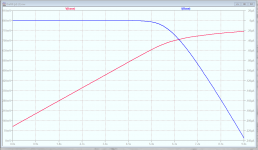
The figure isn't an absolute but the base/emitter junction needs around 0.6 volts before it will begin to conduct, just the same as a single silicon diode needs. When that threshold is reached the junction begins to conduct current and from that point on a very small increase in voltage results in a big increase in current (again just like a diode).
So the base/emitter junction effectively limits or clamps at about 700 millivolts. Push a lot of current through there and you might reach 800 millivolts but it won't go much higher.
We need base current to turn the transistor on. If a transistor has a gain of 50 then we need something like at least 1 milliamp flowing in the base/emitter junction in order for the collector/emitter path to pass 50 milliamps. We could not switch a 1 amp load with a transistor of a gain 50 if we don't supply enough base current.
If you make your 1k base resistor into a 1 meg then the base/emitter junction still clamps as before but now look at the LED current. It is non existent because the current available to the base is far to low. Try it and look at the same voltages and currents.
Try this with your circuit.
1/ Cut the transistor out.
2/ Make the 1k a 3 ohm
3/ Add a diode where the base/emitter junction would be. The anode of the diode to the resistor. Pick a real diode like a MUR460
4/ Make the sim run from 0 to 10 seconds.
Now look at the current in the diode vs time and the voltage across the diode vs time.
Attachments
I actually meant just the diode and resistor, so just one scissor cut needed.
Now try this one which uses an N Channel FET and FET's are 'voltage driven'.
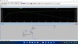
Notice that the gate voltage needs to be higher than 0.7 volts for the FET to turn on (about 3 volts) but also look how the voltage on the gate does not limit like the ordinary transistor (there is a practical limit but we are below that here).
Now make the 1k into a 1meg. The circuit still works the same because the gate draws almost zero current. So this is 'voltage driven'.
Now try this one which uses an N Channel FET and FET's are 'voltage driven'.
Notice that the gate voltage needs to be higher than 0.7 volts for the FET to turn on (about 3 volts) but also look how the voltage on the gate does not limit like the ordinary transistor (there is a practical limit but we are below that here).
Now make the 1k into a 1meg. The circuit still works the same because the gate draws almost zero current. So this is 'voltage driven'.
Attachments

I actually meant just the diode and resistor, so just one scissor cut needed.
Now try this one which uses an N Channel FET and FET's are 'voltage driven'.
Notice that the gate voltage needs to be higher than 0.7 volts for the FET to turn on (about 3 volts) but also look how the voltage on the gate does not limit like the ordinary transistor (there is a practical limit but we are below that here).
Now make the 1k into a 1meg. The circuit still works the same because the gate draws almost zero current. So this is 'voltage driven'.
i guess this is right-had to hunt for the FET but i guess that was part of it.
Attachments
Yes, that's fine.
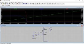
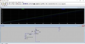
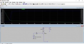
This shows the input voltage and the gate voltage but now with 100 million ohms resistor. Even with that value the two voltages are almost the same. If you look at the difference between them you can work out the current in the resistor.
If you say 0.5 volt difference then we get 0.5/100,000,000 which is 0.000000005 amps which is 5 nano amps. The FET still works perfectly and turns on fully.
Attachments
Heres a good way to show it, some very basic models.
Bipolar Junction Transistors (BJTs) - Analog Electronics Tutorials
10.4: JFET Biasing - Engineering LibreTexts
Bipolar Junction Transistors (BJTs) - Analog Electronics Tutorials
10.4: JFET Biasing - Engineering LibreTexts
Yes, that's fine.
This shows the input voltage and the gate voltage but now with 100 million ohms resistor. Even with that value the two voltages are almost the same. If you look at the difference between them you can work out the current in the resistor.
If you say 0.5 volt difference then we get 0.5/100,000,000 which is 0.000000005 amps which is 5 nano amps. The FET still works perfectly and turns on fully.
Is there a reason why there is little difference when i change R3 to a 100ohm?
Yes, it is because the gate of the FET draws virtually no current from the voltage source driving it.
The gate impedance is so high on a FET that you can turn one on just by touching the gate. Charge from you passes to the gate and the gates stray capacitance is enough to hold that charge and keep the FET on. You can see that effect when testing them.
Think of the FET as working almost on static electricity. You rub a plastic pen on a jumper and you can move bits of paper around just with the static attraction. No direct force needed.
The ordinary transistor needs you to apply physical force (current to flow). to move things. Not a very good analogy I know 🙂
Do you want a new challenge (an easy one 😉)
Go back to your 'draft8' in post #2877 and see if you can switch it around to use a PNP transistor instead of an NPN.
Remember the polarity of a PNP is the opposite to the NPN. So you need to change the transistor (cut it out) and replace it with a PNP and then you must alter three things on the sim to account for the change.
The collector on a PNP has to be more negative than the emitter remember. And think about the LED.
I always found mentally switching to try and figure PNP's out very confusing at first but eventually it will just 'click' and you become used to working with them without even thinking about it.
Is there a reason why there is little difference when i change R3 to a 100ohm?
I've just noticed you said 100 ohm and I was thinking of 100 million ohms.
100 ohm allows more current to flow into the base and when I try that on the sim I see it allows the base voltage to rise quite high.
I'm not sure I agree with that... it should limit much more toward the 800 millivolt level.
Trying a 2N3055 transistor does indeed limit out more as expected. I'm going to agree to disagree with LT on that one. I would expect the smaller transistor to limit much more than they are doing here.
is this right?
Good effort, you got the LED correct.
Now there is actually less to do than you might think starting from the original sim.
1/ The LED needs swapping

2/ Simply make the supply -6.5 volts
3/ Make the input voltage -10 instead of 10
And tomorrow is another day... telly time now.
Attachments

- Home
- Design & Build
- Software Tools
- Installing and using LTspice IV (now including LTXVII), From beginner to advanced