And calculating the old fashioned way...
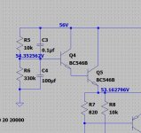
R total equals 10k + 330k which is 340k.
I =V/R which is 56/340,000 giving 0.165 milliamps flowing in the series chain of the two resistors.
Voltage across the 10k is 0.165E-3 * 10,000 giving 1.65 volts.
Voltage across the 330k is 0.165E-3 * 330,000 giving 54.45 volts.
Total of the two equals 56 volts.
NOTE... the actual circuit also has Q4 drawing a tiny base current from the 10k resistor but in this case the value is microscopic and so can be ignored for a manual calculation. It doesn't really alter the practical result.
yes i get it, classic,i used '164' in my calculation but not in microamps
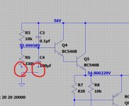
so where the resistor goes to ground is there a reason why there is no voltage the other side of it?
i did a simulation without it in place(i saved a different copy) and the current is alot higher so i guess its there to dissipate some of that current away from the base??
Do you mean R6?
It has 54.3 on one end and nothing on the other because that is ground. Maybe I'm not following you on that 🙂
What current is a lot higher? The current in R5 should fall to almost nothing (42 nano amps) because that is the tiny base current of Q4.
It has 54.3 on one end and nothing on the other because that is ground. Maybe I'm not following you on that 🙂
What current is a lot higher? The current in R5 should fall to almost nothing (42 nano amps) because that is the tiny base current of Q4.
One thought. Every time you alter something you must re-run the sim. Sometimes weird things happen if you cut things out and do not re-run... nothing should alter until you re-run it but I think sometimes it can. Seem to remember something about that.
Do you mean R6?
It has 54.3 on one end and nothing on the other because that is ground. Maybe I'm not following you on that 🙂
What current is a lot higher? The current in R5 should fall to almost nothing (42 nano amps) because that is the tiny base current of Q4.
yes so that answers my question.is that the effect everytime you put one to ground?
im just messing around with it at the moment to see what the effects are by removing or changing values, but keeping the original file and comparing them side by side.
the more i do this the more i will get used to it and understand the concequences of change
im going to have a serious go at guilding something on screen from scratch when i get back after my hols!
im interested for example and trying to understand why the voltages have drasticaly changed from the emitter at Q5 by removing R6 and C4
yes so that answers my question.is that the effect everytime you put one to ground?
All voltages are measured with respect to ground and so you will always see
zero volts (it will say in the lower left corner, this is ground) when you look at anything connected to ground.
In simulation all connections between points are perfect, there are no losses and no volt drops. Voltage sources are perfect to (unless you alter them not to be so) meaning that you can load that 56 volt rail or that input voltage with a load drawing a trillion amps and it will not drop at all.
im just messing around with it at the moment to see what the effects are by removing or changing values, but keeping the original file and comparing them side by side.
the more i do this the more i will get used to it and understand the concequences of change
im going to have a serious go at guilding something on screen from scratch when i get back after my hols!
im interested for example and trying to understand why the voltages have drasticaly changed from the emitter at Q5 by removing R6 and C4
You have to keep playing around to learn 🙂
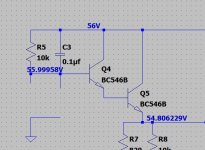
So another puzzle though, the voltage on Q5 emitter should not change much if you remove R6 and C4.
How are you removing them or isolating them. Use the 'scissors' on the top line. Compare the three attached images. You can use 'Edit' and 'Undo' and 'Redo' to put them back.,
am i in the right direction with this?
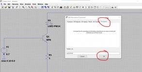
Well it is a valid circuit up to a point. When you set any sim up using the 'Transient' tab you are running what you would see with an oscilloscope, in other words voltage over time.
For a DC analysis we don't need to do that. Try altering your sim by selecting DC opt point as shown here. When you click OK you must then place the new command on the worksheet. So click OK once and then you will find the command attached to the cursor for you to drop anywhere on the page.
Now run the sim and you get a window showing voltages and currents at all nodes. Close that little window and just move the cursor onto any part of the sim to read the voltage etc.
Your circuit as it stands is applying 700mv to the base of an NPN transistor. That is not quite enough to turn the default NPN model on. So you have no current flowing anywhere.
If you make the input 0.8 volts you will get a little LED current flowing.
Make it 1 volt and see what happens.
I'll alter your sim a little later to show how the LED current varies with increasing base current.
Attachments
so i used the scissors to remove the components and links then re ran it.
is thzt diode of mine round the wrong way.
im always thinking electron flow, and it wouldnt work that way would it?
is thzt diode of mine round the wrong way.
im always thinking electron flow, and it wouldnt work that way would it?
how does this type of switch work as i wanted to build something that had a timer circuit so that it can turn things off and on.
ive been working on mechanical and electrical circuits for years so i understand the basic concepts of how to acheive something, but in electronics, switches are, well switches, or transistors, but lamps are just lamps, power supplies are no different, nor how the voltage gets from A to B, its all the other bits that are in there, and why they are there.
for me a transistor for example is a bit like a relay with a coil.A seperate control circuit turns on the coil,often at a lower voltage to control the main relay contactor, so this, although a different technique, is simlar.
so i see a transistor like a switch? the voltage applied to the base turns it on >0.7v? so you could control that voltage aspect by way of an actual switch?
sorry if i am rambling but i feel like i could be quite close to understanding at least some of this.
Attachments

Your diode (LED) is the correct way around. There is a lot to learn 🙂 so take it slowly.
Transistors are current driven rather than voltage driven (like FET's and valves). So let us set your sim up to show how the transistor really works. We swap things around a little and put the 1 ohm in series with the LED while also increasing its value. If we assume 50 milliamps as an absolute maximum for the LED and if we say the LED drops about 2.5 volts then we can say that R=V/I which is (6.5-2.5)/0.05 giving 80 ohms.
Lets also pick a 'real' transistor like a 2N2222. Right click the NPN transistor and select 'Pick New Transistor'. Choose the 2N2222.
So far so good.
Let us now make the voltage source V1 a slowly rising voltage. Right click the V1 and select 'Advanced' and then select 'Pulse'.
Set it as shown.
The initial voltage is zero. This is the voltage it starts from.
The 'on' voltage is 10. This is the voltage it finishes at.
We have 0 for a time delay. This means it starts instantly.
Trise we set to 10. This is 10 seconds to go from 0 to 10 volts.
Tfall we set to 0. The voltage falls back to zero instantly after 10 seconds.
Ton we set to 0. This is 'on' time. How would be how long it stays at 10 volts.
Tperiod we set to 10. This is the time for 1 cycle.
Ncycles we leave blank. It runs for ever.
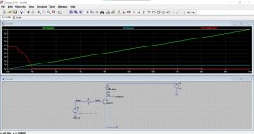
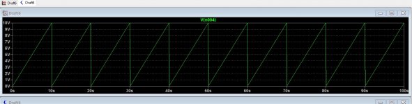
All of that has created a sawtooth voltage as shown.
We need an additional resistor to limit base current, otherwise the transistor would be destroyed (real ones, not simulated ones 😉) We will pick 1k.
Set the sim to run for 10 seconds to cover the time of one cycle and lets see what happens.
Plotting the three voltages shows the input voltage rising. The base voltage limits at about 800 millivolts. This is the Vbe of the transistor (the B-E junction behaves like a diode remember).
The collector volts fall to almost zero as the transistor turns fully on.
Transistors are current driven rather than voltage driven (like FET's and valves). So let us set your sim up to show how the transistor really works. We swap things around a little and put the 1 ohm in series with the LED while also increasing its value. If we assume 50 milliamps as an absolute maximum for the LED and if we say the LED drops about 2.5 volts then we can say that R=V/I which is (6.5-2.5)/0.05 giving 80 ohms.
Lets also pick a 'real' transistor like a 2N2222. Right click the NPN transistor and select 'Pick New Transistor'. Choose the 2N2222.
So far so good.
Let us now make the voltage source V1 a slowly rising voltage. Right click the V1 and select 'Advanced' and then select 'Pulse'.
Set it as shown.
The initial voltage is zero. This is the voltage it starts from.
The 'on' voltage is 10. This is the voltage it finishes at.
We have 0 for a time delay. This means it starts instantly.
Trise we set to 10. This is 10 seconds to go from 0 to 10 volts.
Tfall we set to 0. The voltage falls back to zero instantly after 10 seconds.
Ton we set to 0. This is 'on' time. How would be how long it stays at 10 volts.
Tperiod we set to 10. This is the time for 1 cycle.
Ncycles we leave blank. It runs for ever.
All of that has created a sawtooth voltage as shown.
We need an additional resistor to limit base current, otherwise the transistor would be destroyed (real ones, not simulated ones 😉) We will pick 1k.
Set the sim to run for 10 seconds to cover the time of one cycle and lets see what happens.
Plotting the three voltages shows the input voltage rising. The base voltage limits at about 800 millivolts. This is the Vbe of the transistor (the B-E junction behaves like a diode remember).
The collector volts fall to almost zero as the transistor turns fully on.
Attachments

It is not wrong, but it doesn't quite do what we want.
Run the sim and look at the time scale on the bottom of the graph. It runs from 0 to 100 milliseconds. It is doing exactly what you have told it to do. We really want to see the full 10 seconds of the complete input cycle.
Can you see why? Open the 'Edit Simulation Cmd' Window. You need to alter one thing.
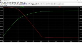
Also try this when you have it figured out 🙂 Set the simulation to run over the critical turn on point of the transistor. This is where the rising base voltage begins to turn the transistor on.
Look at the base voltage and the LED current. It should look like this. The current goes from zero to a maximum over a very small change in applied base voltage. Current scale on the right of the graph.
Run the sim and look at the time scale on the bottom of the graph. It runs from 0 to 100 milliseconds. It is doing exactly what you have told it to do. We really want to see the full 10 seconds of the complete input cycle.
Can you see why? Open the 'Edit Simulation Cmd' Window. You need to alter one thing.
Also try this when you have it figured out 🙂 Set the simulation to run over the critical turn on point of the transistor. This is where the rising base voltage begins to turn the transistor on.
Look at the base voltage and the LED current. It should look like this. The current goes from zero to a maximum over a very small change in applied base voltage. Current scale on the right of the graph.
Attachments
Poundy, On the real workbench, I would take a potmeter instead of the 10K fixed top resistor of the voltage divider.
Then you turn till the current flows (and happens what you want. Drive a LED, easy to see). In the sim you can use the .step command to do the same, but unfortunately the LED will not light up on screen, not even burn down 😱 ...
Then you turn till the current flows (and happens what you want. Drive a LED, easy to see). In the sim you can use the .step command to do the same, but unfortunately the LED will not light up on screen, not even burn down 😱 ...
ill try this out tomorrow now im back from my hols 🙂It is not wrong, but it doesn't quite do what we want.
Run the sim and look at the time scale on the bottom of the graph. It runs from 0 to 100 milliseconds. It is doing exactly what you have told it to do. We really want to see the full 10 seconds of the complete input cycle.
Can you see why? Open the 'Edit Simulation Cmd' Window. You need to alter one thing.
Also try this when you have it figured out 🙂 Set the simulation to run over the critical turn on point of the transistor. This is where the rising base voltage begins to turn the transistor on.
Look at the base voltage and the LED current. It should look like this. The current goes from zero to a maximum over a very small change in applied base voltage. Current scale on the right of the graph.
like this?It is not wrong, but it doesn't quite do what we want.
Run the sim and look at the time scale on the bottom of the graph. It runs from 0 to 100 milliseconds. It is doing exactly what you have told it to do. We really want to see the full 10 seconds of the complete input cycle.
Can you see why? Open the 'Edit Simulation Cmd' Window. You need to alter one thing.
Also try this when you have it figured out 🙂 Set the simulation to run over the critical turn on point of the transistor. This is where the rising base voltage begins to turn the transistor on.
Look at the base voltage and the LED current. It should look like this. The current goes from zero to a maximum over a very small change in applied base voltage. Current scale on the right of the graph.
Attachments
Yes but run the sim from 0 seconds and not 1 seconds. The transistor B-E voltage clamps at around 800 millivolts.
In fact look at the first 2 seconds only. Set the sim to run from 0 to 2 seconds and look at the voltage source and the base volts.
(Can't do a screen snip just this moment... playing with and clean installing W11 🙂)
In fact look at the first 2 seconds only. Set the sim to run from 0 to 2 seconds and look at the voltage source and the base volts.
(Can't do a screen snip just this moment... playing with and clean installing W11 🙂)
- Home
- Design & Build
- Software Tools
- Installing and using LTspice IV (now including LTXVII), From beginner to advanced