Now that PWL is a very interesting building stone.
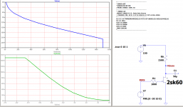
here my use to find a fitting bias point for a preamp stage with a 2SK60.
I am curious if that could be used to create a Frankentracer simulation? [That leverages a X-Y plot in a Tektronix scope so the plot is turned 90 degrees in some way. ]
here my use to find a fitting bias point for a preamp stage with a 2SK60.
I am curious if that could be used to create a Frankentracer simulation? [That leverages a X-Y plot in a Tektronix scope so the plot is turned 90 degrees in some way. ]
Attachments
Last edited:

Attachments
Last edited:
so like this then.
That's it. So ground is still our reference point but now all voltages are negative with respect to ground. The base/emitter voltage levels out at about negative 800mv
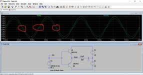
Here is a circuit combining an NPN and a PNP. This is a basic Class B push pull output stage. The load could be a speaker.
Can you see why there is massive distortion around the zero volt point of the output signal?
Attachments
Now that [V=10k*(v(Vdrain)-Vd)] is a handsome way to find a wanted bias point ! 🙂
That's it. So ground is still our reference point but now all voltages are negative with respect to ground. The base/emitter voltage levels out at about negative 800mv
Here is a circuit combining an NPN and a PNP. This is a basic Class B push pull output stage. The load could be a speaker.
Can you see why there is massive distortion around the zero volt point of the output signal?
See
Attachments
Mooly, I do not want to neg you to much, but what is the point?
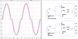
The resistor acts as a feedback, consider a source of 1kVAC, a Hfe of 100 and a resistor of several kOhm, this will reduce the distortion by an other factor of 10 (or more, I did do no simulations of that). In fact the only thing it does do is show that the transistor is a current controlled device.
The resistor acts as a feedback, consider a source of 1kVAC, a Hfe of 100 and a resistor of several kOhm, this will reduce the distortion by an other factor of 10 (or more, I did do no simulations of that). In fact the only thing it does do is show that the transistor is a current controlled device.
I suppose it adds a real world factor into things seeing as the voltage source has unlimited current delivery in simulation. It would show how gain differences in different transistors affect things.
I'm also thinking more what might happen (and I haven't tried) if you simmed say a 10 ohm or a 1 ohm load. The voltage source might possibly drive it a bit unrealistically compared to real world parts... which would be letting the magic smoke out 😀
I'm also thinking more what might happen (and I haven't tried) if you simmed say a 10 ohm or a 1 ohm load. The voltage source might possibly drive it a bit unrealistically compared to real world parts... which would be letting the magic smoke out 😀
would you fit a cap to ground to filter it?That's it. So ground is still our reference point but now all voltages are negative with respect to ground. The base/emitter voltage levels out at about negative 800mv
Here is a circuit combining an NPN and a PNP. This is a basic Class B push pull output stage. The load could be a speaker.
Can you see why there is massive distortion around the zero volt point of the output signal?
That is a good circuit to learn with. I can see it looks like a dual tracking regulator when its done.

Not yet it doesn't.
(have a look at Q2 and the supply to Q1)
does this work?
Not yet it doesn't.
(have a look at Q2 and the supply to Q1)
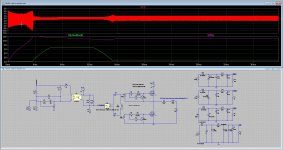
hi all I have tryed a LCC smps does nice even feedback works, output 12,6 320, 120, 120 volts.
Does start soft with frequency above resonance dropping slowly until it locks by feedback and voltage.
However I have some kind of oscillation on left of sinusoidal promary (in resonance) signal from switches..
Does start soft with frequency above resonance dropping slowly until it locks by feedback and voltage.
However I have some kind of oscillation on left of sinusoidal promary (in resonance) signal from switches..
Attachments
Last edited:
I am NOT a regular LTspice user, know very little about how it's put together and need help. A friend sent me an .asc file to model a circuit I'm interested in and I have found a solution using it that I'm happy with.
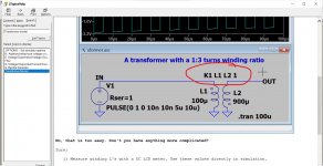
The circuit has an inductor with dual coils in parallel, the directive "K1 L1 L2 1" and a value on each coil of .5 Henry.
However, I don't know whether the interface acts as if I'm putting in the independent 'as wound' value for each individual coil (ie. each coil on its own is 0.5. Henry) or whether that value is meant to be the result of the parallel configuration.
In other words, in looking for a real part to build the circuit, Do I look for a nominal 2 Henry choke with dual 1 Henry coils, or a nominal 1 Henry choke with two 0.5 Henry coils?
Thanks very much ! ! !
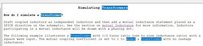
That sounds a bit like a transformer setup. If you open LT, click 'Help' and search for 'Transformer Model' it will explain a little about it. The example is available in the 'Examples' folder in your LT Documents folder.
Attachments
I am NOT a regular LTspice user, know very little about how it's put together and need help. A friend sent me an .asc file to model a circuit I'm interested in and I have found a solution using it that I'm happy with.
The circuit has an inductor with dual coils in parallel, the directive "K1 L1 L2 1" and a value on each coil of .5 Henry.
However, I don't know whether the interface acts as if I'm putting in the independent 'as wound' value for each individual coil (ie. each coil on its own is 0.5. Henry) or whether that value is meant to be the result of the parallel configuration.
In other words, in looking for a real part to build the circuit, Do I look for a nominal 2 Henry choke with dual 1 Henry coils, or a nominal 1 Henry choke with two 0.5 Henry coils?
Thanks very much ! ! !
Attachments
However, I don't know whether the interface acts as if I'm putting in the independent 'as wound' value for each individual coil (ie. each coil on its own is 0.5. Henry) or whether that value is meant to be the result of the parallel configuration.
In other words, in looking for a real part to build the circuit, Do I look for a nominal 2 Henry choke with dual 1 Henry coils, or a nominal 1 Henry choke with two 0.5 Henry coils?
Windings on the same core do not shunt each other when in parallel. If you have 2 1H windings and you put them in parallel, you still have a 1H inductor because they are on the same core. So it's not so much how LTspice treats inductors as it is their physical operation. This confused me once too.
That sounds a bit like a transformer setup. If you open LT, click 'Help' and search for 'Transformer Model' it will explain a little about it. The example is available in the 'Examples' folder in your LT Documents folder.
Hi Mooly
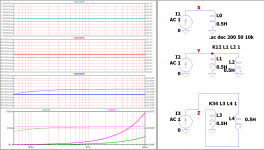
I did a resonance smps sim, and there the transformer leak induction is used together with a external coil, it can also be done with a slotted bobine who has windings left and right of each other to get leak induction.
I have done it different for sim, I did use a K of 1 to get perfect coupling and use Lp of transformer, that is own induction with included leak induction who is Lm + Lr.
I did use also K = 0.9 pr such te get leak induction but I can not see or adjust the amount this way. Did I sim it right with what I say about K = 1?
It did sim and voltages did near the calculated ones, so I think it does work this way I did, see previous post with pic.
thanks.
- Home
- Design & Build
- Software Tools
- Installing and using LTspice IV (now including LTXVII), From beginner to advanced