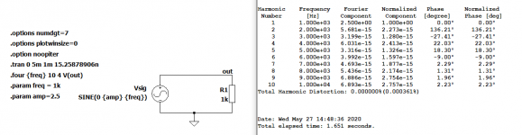
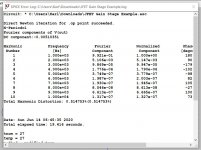
Here's an example. It shows the ideal 0% distortion.
The math for the timestep is: sample time / 262144.
So, four cycles at 1KHz is 4ms / 262144 = 15.25878906ns. This is probably an overkill. You could use some factor of 262144 and likely get the same result. I'm also starting after 1 cycle to let the initial operating conditions settle. Probably not needed in a circuit like this without any capacitors. But its shown for illustrative purposes.
Attachments
Last edited:
Ciuffoli's power follower simulation
Hi, I'm running a simulation of Ciuffoli's power follower, all measurements are very well but in measuring the distortion I get the sinusoids of Vin and Vout equal and perfectly superimposed, what is not working?
Thanks
Hi, I'm running a simulation of Ciuffoli's power follower, all measurements are very well but in measuring the distortion I get the sinusoids of Vin and Vout equal and perfectly superimposed, what is not working?
Thanks
That sounds right. What are you expecting from a power buffer? Attaching a schematic or asc file would help.
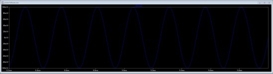
Looks about right to me as well. As Brian says, it's a buffer. Voltage gain of <1 but lots of current gain.
Thanks a lot bordodynov and brian92fs, appreciate the insights and help!! Will go and play with the options to understand better
Sorry missed to answer sooner, somehow i completely overlooked that i had asked that question....
Many thanks!
Sorry missed to answer sooner, somehow i completely overlooked that i had asked that question....
Many thanks!
Hello, Can you help me setup a asc file to measure distortion for a simple jfet gain stage?
Because I found this file but I don't know how to use it.
https://www.diyaudio.com/forums/software-tools/101810-spice-simulation-83.html#post1744406
Because I found this file but I don't know how to use it.
https://www.diyaudio.com/forums/software-tools/101810-spice-simulation-83.html#post1744406
Hello, Can you help me setup a asc file to measure distortion for a simple jfet gain stage?
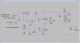
This file is about as simple as it gets; a simple common source JFET stage. LTspice has a built-in model for the 2N5484 so this file will simulate without any external files.
The stage is set up for a gain of about x10. The key to getting a distortion chart is the .four statement. This statement tells LTspice to measure harmonic distortion at the Out terminal at 1 KHz, and to include 10 harmonics in the analysis. After performing a transient simulation, press Ctrl-L to bring up a "log" file; this will display a THD chart.
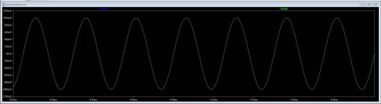
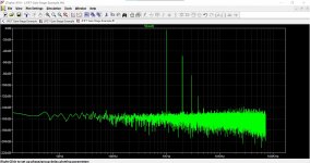
You can also look at the distortion products in the waveform display. From the "View" menu click on the FFT item and then select V(out) as the waveform you want to examine.
I hope this is helpful.
Attachments
Thank you. It's in post 823.Which post is the file in?
Thank you so much for taking the time to setup this for me ! I think I understand better with these explanations.This file is about as simple as it gets; a simple common source JFET stage. LTspice has a built-in model for the 2N5484 so this file will simulate without any external files.
The stage is set up for a gain of about x10. The key to getting a distortion chart is the .four statement. This statement tells LTspice to measure harmonic distortion at the Out terminal at 1 KHz, and to include 10 harmonics in the analysis. After performing a transient simulation, press Ctrl-L to bring up a "log" file; this will display a THD chart.
You can also look at the distortion products in the waveform display. From the "View" menu click on the FFT item and then select V(out) as the waveform you want to examine.
I hope this is helpful.
To use it I run the simulation. I right clic on the waveform then select "view > FFT". And then to have the actual numbers I view the error log. Right ?
Almost. To see the FFT display you need to be in the waveform window. From there, you will see an FFT item in its View menu. If you are in the schematic window, FFT is not an available option in its View menu.
Thank you. It's in post 823.
Thank you so much for taking the time to setup this for me ! I think I understand better with these explanations.
To use it I run the simulation. I right clic on the waveform then select "view > FFT". And then to have the actual numbers I view the error log. Right ?
 got it, and yes, right click and FFT and Error Log.
Try and follow posts 19 and 20 in this thread:
Installing and using LTspice IV (now including LTXVII). From beginner to advanced.
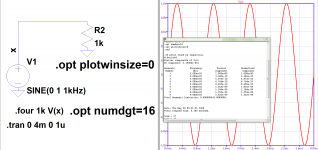
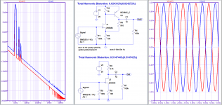
One thing we can do is to increase the coupling cap value in the sim which will greatly improve the FFT result. Lets make it '1' which is 1 Farad (don't use 1F which is actually 1 Femto Farad).
We will also run the sim for much longer, say 800ms and save data from say 400ms. Now we can get an FFT like this.
Attachments
Thanks, but my example wasn't intended to present the best possible circuit. I was answering a question about how to display distortion in a JFET stage and showed the simplest circuit I could produce for that purpose. But your modification is a nice circuit for someone that is trying to build a real JFET gain stage.
I have a sim that runs for a bit than stops and gives the message "min timestep too small 10^-17s". All it takes sometimes to get it to run is to change a cap value? Any ideas whats up? I cant find anywhere to set min timestep.
Post your .asc file.
tommost
tommost
I have a sim that runs for a bit than stops and gives the message "min timestep too small 10^-17s". All it takes sometimes to get it to run is to change a cap value? Any ideas whats up? I cant find anywhere to set min timestep.
- Home
- Design & Build
- Software Tools
- Installing and using LTspice IV (now including LTXVII), From beginner to advanced