Right now my sims are all running. I tweak them till they do before i save. But i keep getti.ng the message so Ill post one soon. Thanks.
A general tip - always check the option for start all external voltages at 0 V in the dot tran dialog. Otherwise weird things happen.
tommost
tommost
Right now my sims are all running. I tweak them till they do before i save. But i keep getti.ng the message so Ill post one soon. Thanks.
It is not telling you your timestep is too small. This is a mistake in communication from the programmer.
LTspice automatically reduces the timestep as necessary to accurately simulate sharp waveforms. Your simulation however is creating a waveform which gets sharper the smaller the timestep is. Therefore LTspice keeps reducing the timestep until it goes below 10^-17s, at which point it decides it is futile and gives up.
This might be because you have floating nodes or Norton/Thevenin equivalence issues or just are running into limitations in the device models.
Question to you guys: what is the best way to find out which part of a circuit causes most of the noise? Do you have to do lots of sims on all nodes and compare, or is there a smarter way?
Jan
Jan
Are you referring to a signal processing circuit like an amplifier or a power supply?
In my experience LTSpice underestimates noise in power supplies, especially switching supplies. First because capacitor ESR is only roughly modeled so output filtering looks much better than it is, and second because ground is perfectly zero impedance.
In signal processing you also run into the problem of imperfect models.
Now I can just imagine Mike E. bristling at these statements, if you use perfect models you'll get correct results. But the problem is that you end up with such complex circuits that simulation gets very slow.
My sadly departed friend Jim Williams used to say that if you work with straightforward circuits straightforward simulations give you accurate results. It's when you're trying to eke out that last bit of performance that there's no substitute for bench work.
Good luck Jan!
tommost
Question to you guys: what is the best way to find out which part of a circuit causes most of the noise? Do you have to do lots of sims on all nodes and compare, or is there a smarter way?
Jan
Question to you guys: what is the best way to find out which part of a circuit causes most of the noise? Do you have to do lots of sims on all nodes and compare, or is there a smarter way?
Jan
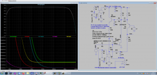
You can make it this way, a circuit I just happen to have on the screen.
On the left side, lower half:
green is the noise performance overall, scaled to the input.
blue is the influence of the gate resistor, it is horrible. That would go
away when we increase the input capacitor from 10n to 10u. Then the
noise voltage of R11 would be shorted for 3 more decades through the
low impedance DUT. Note that we do not need a larger capacitor for
bandwidth reasons. It is really bad for the settling time.
yellow is the contribution of the 32 parallel FETs.
purple is the influence of voltage noise on VCC. R1 = 60 Ohm generates
1nV/rtHz. The 0.1uV dc offset avoids a divide by 0 disaster in Spice or
sth. like that. the voltage controlled voltage source scales that to 5nV/rtHz
and that is added to the otherwise clean Vcc. When we remove the 10 mF
capacitor C, we can see that 5nV/rt Hz do matter.
The same is done to Vee, there the noise has less influence.
G1 scales the 1nV/rt Hz of the Vee noise generator to 44 fA to simulate
a noise current from the JFET gate.
There are always 3 traces because of the 3 temperatures.
Does anybody here know how to fix the nV/rt Hz scale to the values chosen?
I'm sick of undoing the auto scale after each simulation.
cheers, Gerhard
Attachments
Last edited:
Actually my question was to the method to measure noise in LTspice ...
I now understand that you can click on a part and the noise contribution to that part is shown, right?
So what is then the purpose of the .noise command, what does that do? Like .noise V(bout) V3 oct 25 100 100k where bout is a circuit node?
Jan
I now understand that you can click on a part and the noise contribution to that part is shown, right?
So what is then the purpose of the .noise command, what does that do? Like .noise V(bout) V3 oct 25 100 100k where bout is a circuit node?
Jan

Ahem ... I did now, and I think I got it.
What the Help doesn't discuss is that you can plot a part's noise contribution by clicking on it.
(It says you can do it but not how). I guess that is then output-referred, unless divided by gain?
Jan
What the Help doesn't discuss is that you can plot a part's noise contribution by clicking on it.
(It says you can do it but not how). I guess that is then output-referred, unless divided by gain?
Jan
Last edited:
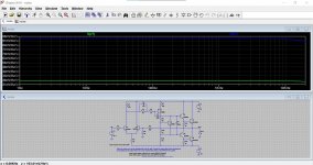
I really don't know on that one Jan. The example seems to have all the resistors 'clickable' in that a noise plot comes up for them all but I'm not sure how its interpreted because the 50k feedback resistor comes back as 27nV/Hz vs 94 for the 5k.
The files say it is referenced to the output... that'll keep you busy 😉
The files say it is referenced to the output... that'll keep you busy 😉
Attachments
It is not telling you your timestep is too small. This is a mistake in communication from the programmer.
LTspice automatically reduces the timestep as necessary to accurately simulate sharp waveforms. Your simulation however is creating a waveform which gets sharper the smaller the timestep is. Therefore LTspice keeps reducing the timestep until it goes below 10^-17s, at which point it decides it is futile and gives up.
This might be because you have floating nodes or Norton/Thevenin equivalence issues or just are running into limitations in the device models.
Thanks for the explanation. Will watch for these things.
Ahem ... I did now, and I think I got it.
What the Help doesn't discuss is that you can plot a part's noise contribution by clicking on it.
(It says you can do it but not how). I guess that is then output-referred, unless divided by gain?
Jan
IME when you click on a part its that parts contribution to the total noise. In some cases it may not be clear but for a feedback network the lower resistance will contribute more because the feedback resistors contribution is reduced by the attenuation. You can scale that back to the input like Gerhard has (nice trick). You pretty quickly determine which parts are not significant. You do need good models that will show real noise contribution. Not all opamp models are good (surprise).
That makes sense. The reason I got into this is I have a circuit with a JFET with a large drain load resistor >50k which dominates the noise, and I want to see how that changes when I replace that resistor with a CCS (~0.6mA).
It's funny how far you can get in life without having ever having looked in detail at this stuff 😎
Jan
It's funny how far you can get in life without having ever having looked in detail at this stuff 😎
Jan
Last edited:
That may dominate the absolute value of the noise, but the input
signal is amplified by gm * 50K, so it doesn't matter. The output
resistance of the FET is in par to the 50K, the numbers will be smaller.
That's what cascodes are for.
signal is amplified by gm * 50K, so it doesn't matter. The output
resistance of the FET is in par to the 50K, the numbers will be smaller.
That's what cascodes are for.
Last edited:
That makes sense. You always should consider input referred noise. From that point of view I would not expect a significant improvement by using a current source as drain load. Specially with these fantastic low noise & high gm types like 2SK170 and the likes.
After having your sim completed and adjusted the scales in your image, click on the Image, then click "Plot Setting" in the command line, click on "Save Plot Settings" with the proposed name or with your own selected name and finish by clicking on "Save".Does anybody here know how to fix the nV/rt Hz scale to the values chosen?
I'm sick of undoing the auto scale after each simulation.
cheers, Gerhard
Next time you run a sim, click on the image, click "Plot Settings" and "Reload Plot Settings", and there you are with all the scales adjusted as in the previous image that you saved.
Hans
I do not now if more people has the problem of a crashing 64 bit LTspice, but I have, it just crash when I close the program, of stop the simulation.
This version has never be stable in fact.
regards
This version has never be stable in fact.
regards
That is strange. I use it on 3 different PCs, all Win10/64bit, never had any crashes.
Jan
When I do normal sims, it just work fine, but when I do close the program a crash occurs, maybe a software conflicting .dll
regards
- Home
- Design & Build
- Software Tools
- Installing and using LTspice IV (now including LTXVII), From beginner to advanced