Hey! Many thanks, Karl. Always so cooperative. But the versions downloadable are for 7 in advance.
Last edited:
Osvaldo, look at the third line of downloads for LTSpice; its for Windows XP. I downloaded it yesterday.

Fortunately I found in an old pen-drive a copy of the original version, so I didn't need to reinstall it. Also, I recovered the circuits I did.
In any case, many thanks for the inputs.
In any case, many thanks for the inputs.
I have found a simulation model of a sic mosfet who is interesting, but ltspice do not sim with it well, no graph and it error later on.
Did try everything with no succes, it just show no graph, with the others it do fine so model of that mosfet is not oke maybe some ltspice professors here can look at it.
thanks.
Did try everything with no succes, it just show no graph, with the others it do fine so model of that mosfet is not oke maybe some ltspice professors here can look at it.
thanks.
Attachments
Example:
.model C2M0025120D_AB VDMOS(Rg=1.1 Vto=2.25 Rd=-5m Rs=20m Rb=6.7m Kp=2.6 Ksubthres=.1 Mtriode=3 Theta=20m Lambda=40m Cgdmin=15p Cgdmax=2n Cgs=2825p tt=15n ibv=1.5m nbv=20 a=0.7 is=3.6p cjo=2.52n bv=1600 m=0.368 EG=3.26 vj=0.6 n=3.9 Vds=1200 Ron=25m
.model C2M0025120D_AB VDMOS(Rg=1.1 Vto=2.25 Rd=-5m Rs=20m Rb=6.7m Kp=2.6 Ksubthres=.1 Mtriode=3 Theta=20m Lambda=40m Cgdmin=15p Cgdmax=2n Cgs=2825p tt=15n ibv=1.5m nbv=20 a=0.7 is=3.6p cjo=2.52n bv=1600 m=0.368 EG=3.26 vj=0.6 n=3.9 Vds=1200 Ron=25m
Example:
.model C2M0025120D_AB VDMOS(Rg=1.1 Vto=2.25 Rd=-5m Rs=20m Rb=6.7m Kp=2.6 Ksubthres=.1 Mtriode=3 Theta=20m Lambda=40m Cgdmin=15p Cgdmax=2n Cgs=2825p tt=15n ibv=1.5m nbv=20 a=0.7 is=3.6p cjo=2.52n bv=1600 m=0.368 EG=3.26 vj=0.6 n=3.9 Vds=1200 Ron=25m
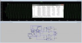
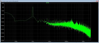
I have tryed these one.
results from a allfet circlotron see pictures, not bad.
Attachments
Hi, I was trying to determinate the output impedance of a circuit, following the instructions here: 15/ Measuring amplifier output impedance. Post #214
the circuit is this, (attachment), from an idea of fellow member Ketje
sure I'm missing some crucial detail, because I'nt getting nothing resembling an impedance plot
I'm trying to know if this circuit is usable with a certain "difficult" SS amplifier input stage
Hope someone can point me the right direction
Cheers
J.
Attachments
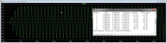
I've taken your schematic and done the following:
1. added I1 across the output, set to AC=1
2. zeroed out the AC component of the input source
If you run an AC simulation, and look at Vout (on a non-dB basis), the resultant voltage numbers correspond to the output impedance.
I can double check it if you can include your tube models.
1. added I1 across the output, set to AC=1
2. zeroed out the AC component of the input source
If you run an AC simulation, and look at Vout (on a non-dB basis), the resultant voltage numbers correspond to the output impedance.
I can double check it if you can include your tube models.
Attachments
I can double check it if you can include your tube models.
Sure I can, and many many thanks
(change .txt to .inc if necessary)
Attachments
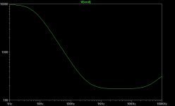
Ok, so this is the graph as it is supposed to be? mmm..
some 3K at 20Hz, a good 180R most of the time, climbing to +300R at VHF ?
some 3K at 20Hz, a good 180R most of the time, climbing to +300R at VHF ?
Attachments
Last edited:
Looks right to me...the only differences are in the format of the reporting:
1. you reported the results over a wider bandwidth, and
2. you show both magnitude and phase, while I'm showing only magnitude.
But, it looks quite reasonable.
1. you reported the results over a wider bandwidth, and
2. you show both magnitude and phase, while I'm showing only magnitude.
But, it looks quite reasonable.
It looks like it can hit the desired target: "The input resistance is ~10K, but the source impedance is preferably kept below 1K, because of the base current modulation caused by the bias servo."
Anyway, the instructions posted where right, I forgot to zeroing the signal source. Great instructable.
Thank You very much
J.
Anyway, the instructions posted where right, I forgot to zeroing the signal source. Great instructable.
Thank You very much
J.
Last edited:
@Mosquito: qué pasó con el Rastrojero Diesel en tu foto?
What happen with the old Truck in your avatar?
What happen with the old Truck in your avatar?
- Home
- Design & Build
- Software Tools
- Installing and using LTspice IV (now including LTXVII), From beginner to advanced